Fuel reforming apparatus and fuel cell system

a technology of fuel cell and fuel reforming apparatus, which is applied in the direction of machines/engines, process and machine control, and combustion gas production, etc., can solve the problems of uneven distribution of concentration in gas, difficult adjustment of supply amount ratio, uneven distribution of supply amount, etc., to achieve easy vaporization of gasoline, enhance the effect of stabilizing the mixture ratio, and stabilize the mixture sta

Inactive Publication Date: 2004-11-18
TOYOTA JIDOSHA KK
View PDF8 Cites 10 Cited by
  • Summary
  • Abstract
  • Description
  • Claims
  • Application Information

AI Technical Summary

Benefits of technology

0074] According to the thus configured fuel cell system 10 in the embodiment, the gasoline which is the reformed fuel is stored as the premixed fuel formed by mixing the gasoline and the water at the predetermined ratio. Accordingly, it is possible to easily vaporize the gasoline and the water at the predetermined mixture ratio, and the configuration for vaporizing the gasoline and the water at the predetermined ratio can be simplified. Also, the ratio between the gasoline and the water which are to be supplied to the reformer 26 can be stabilized. Since the gasoline and the water are sufficiently mixed at the predetermined ratio and then vaporized, it is possible to prevent the mixture ratio between the gasoline and the water from being different from the predetermined ratio. Especially, in the embodiment, the gasoline and the water are emulsified using the additive agent such as the surface active agent (the emulsifier). Accordingly, even when the hydrophobic liquid hydrocarbon such as the gasoline is used as the reformed fuel, it is possible to further stabilize and maintain the mixture state of the reformed fuel and the water, and the effect of stabilizing the mixture state can be obtained remarkably.
0075] In the embodiment, since the premixed fuel which has been emulsified using the surface active agent is sprayed to the high-temperature vaporizing portion 22, the premixed fuel having the predetermined mixture ratio can be vaporized instantaneously. Accordingly, there is no possibility that the value of S / C becomes an undesirable value due to the operation of vaporization. Thus, it is possible to further enhance the effect of stabilizing the mixture ratio between the gasoline and the water (the S / C ratio in the reformer 26) which are to be supplied to the reformer 26.
0076] In addition, when the air is further supplied to the reformer 26, the premixed fuel and the air, both of which are in the form of vapor, are mixed with each other in the vaporizing portion 22. Accordingly, the required mixture ratio can be realized easily. Further, since the first heating portion 24 for heating the vaporizing portion 22 and the reformer 26 is provided, during starting of the fuel cell system 10, by spraying the premixed fuel to the vaporizing portion 22 whose temperature has been increased and by supplying the premixed fuel to the reformer 26, the oxidation reaction and the reforming reaction can be started promptly. Therefore, compared with a case in which the liquid reformed fuel and the water are vaporized using a predetermined heat source, the time until the start of the reaction during starting can be greatly reduced.
0077] In the embodiment, the mixture ratio in the premixed fuel is set to 0.5. Therefore, even when the premixed fuel is supplied to the reformer 26 without adding steam, it is possible to actually prevent soot from being generated in the reformer 26. Accordingly, there is no possibility that the activity of the reforming reaction is reduced and the reforming catalyst deteriorates due to adhesion of soot to the reforming catalyst. Thus, durability of the fuel reforming apparatus 12 can be enhanced. Also, by maintaining the value of the S / C in the premixed fuel in the range in which hindrance to the reforming reaction does not occur, and by suppressing the value as low as possible in the range, it is possible to enhance the efficiency of the oxidation reaction which proceeds in the reformer 26 during starting so as to enhance the efficiency during warming-up.
0078] Further, in the embodiment, it is possible to supply the water to the reformer 26 independently of the premixed fuel. Accordingly, by further supplying water to the premixed fuel, it is possible to make the value of the S / C during the reforming reaction come closer to the optimum value so as to enhance the reforming efficiency. In this case, the humidifying module 38 is used in order to further supply the water to the premixed fuel. Therefore, it is possible to supply the water in the form of steam, and it is not necessary to provide a special configuration for vaporizing the water which is further to be supplied to the premixed fuel. Also, it is not necessary to further consume heat energy for vaporizing the water.
0079] As mentioned above, by storing the premixed fuel in which the S / C is set such that the reforming reaction proceeds without hindrance even if the water is not further supplied and by proceeding with the reforming reaction while replenishing the steam as necessary, it is possible to maintain the reforming reaction in a good condition at all times even when the load fluctuates. For example, even when the load requirement increases abruptly, and the amount of steam corresponding to the increase cannot be added immediately, since the predetermined amount of water has been obtained as the premixed fuel, there is no possibility that an inconvenience occurs in the reforming reaction due to water shortage.

Problems solved by technology

When hydrophobic liquid hydrocarbon fuel such as gasoline was supplied for the reforming reaction as the reformed fuel, it was particularly difficult to adjust the ratio of supply amount between the hydrocarbon fuel and the water so as to be within the predetermined range.
Since the hydrophobic liquid hydrocarbon fuel are not mixed with water easily, even when predetermined amounts of the hydrophobic liquid hydrocarbon fuel and the water are mixed with each other in piping, distributions thereof are uneven.
Accordingly, when the hydrophobic liquid hydrocarbon fuel and the water are vaporized, concentration distributions in gas are uneven.
However, providing the agitating portion in addition to the fuel tank and the vaporizer causes a problem that a configuration for supplying the reformed fuel to a reformer becomes more complicated.
Since the water tank is not provided, and the required amount of water is obtained using the water generated in the system, there is no possibility that the water in the water tank is frozen when a temperature is low and the reforming reaction is hindered.

Method used


Image

  • Fuel reforming apparatus and fuel cell system
  • Fuel reforming apparatus and fuel cell system
  • Fuel reforming apparatus and fuel cell system

Examples


first embodiment

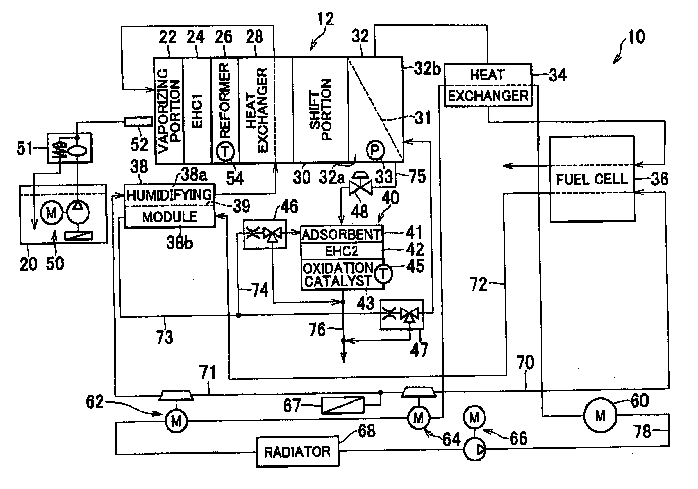
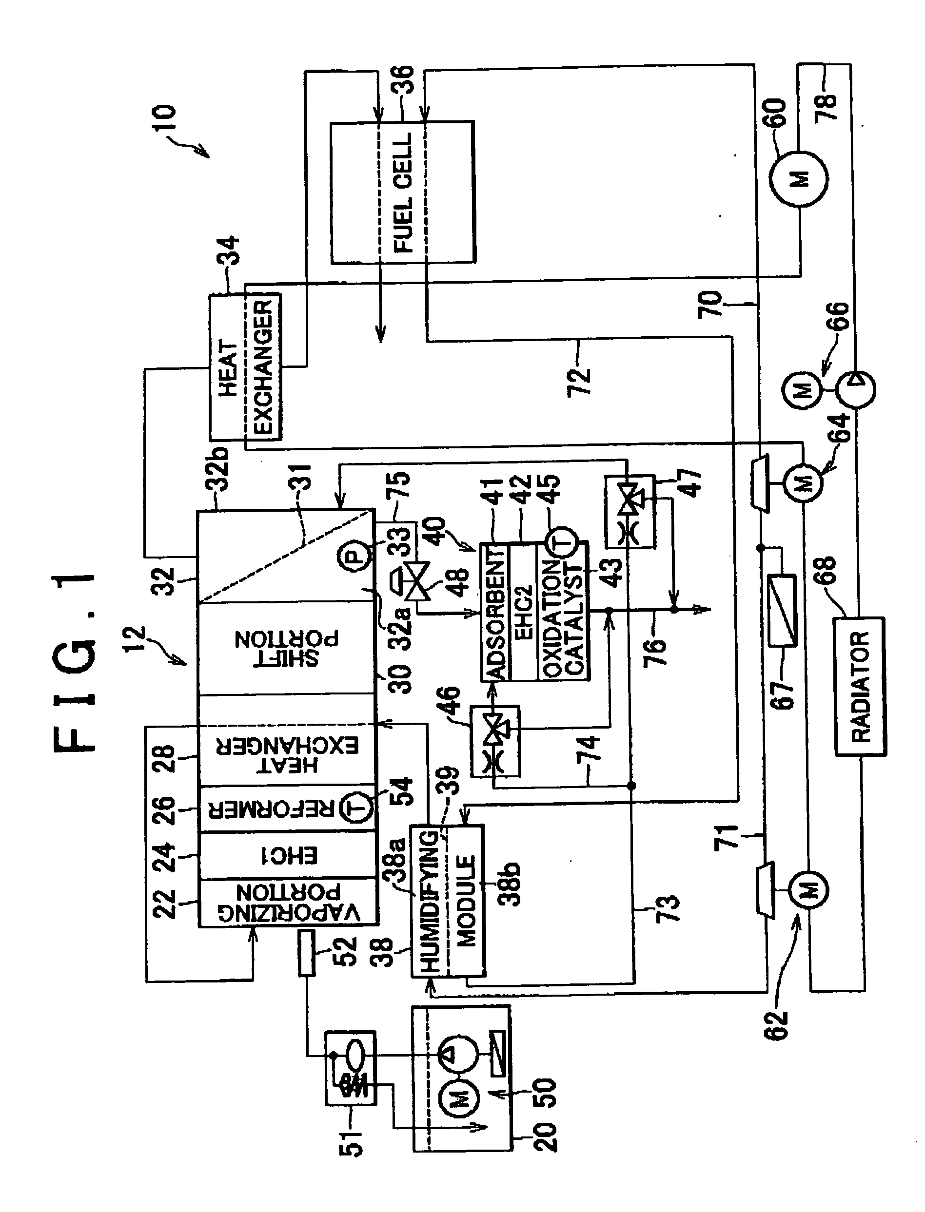
[0039] FIG. 1 is a diagram schematically showing a configuration of a fuel system 10 which is a preferred embodiment of the invention. The fuel cell system 10 is mounted on a vehicle, and is used as a power supply for driving the vehicle. The fuel cell system 10 includes a fuel cell 36 and a fuel reforming apparatus 12 for generating hydrogen to be supplied to the fuel cell 36. The fuel reforming apparatus 12 includes a premixed fuel tank 20, a vaporizing portion 22, a first heating portion 24 (EHC1), a reformer 26, a heat exchanger 28, a shift portion 30, and a hydrogen separating portion 32.

[0040] The premixed fuel tank 20 stores premixed fuel formed by mixing gasoline and water at a predetermined ratio. In the embodiment, the premixed fuel is used which is formed by mixing gasoline and water such that a ratio of the number of molecules of the water with respect to the number of carbon atoms in the gasoline (hereinafter, the ratio will be referred to as an S / C) is 0.5. In this ca...

second embodiment

[0082] D.

[0083] FIG. 3 is a diagram schematically showing a configuration of a fuel cell system 110 according to a second embodiment of the invention. Since the fuel cell system 110 according to the second embodiment has a configuration similar to that of the fuel cell system 10 according to the first embodiment, the same reference numbers are assigned to the common components, and detailed descriptions thereof will be omitted. In the fuel cell system 110 according to the second embodiment, the same control as the fuel cell system 10 according to the first embodiment is performed. Hereafter, only the configurations of the fuel cell system 110 according to the second embodiment which are different from those of the fuel cell system 10 according to the first embodiment will be described.

[0084] In the fuel cell system 110, the premixed fuel stored in the premixed fuel tank 20 passes through a heat exchanger 134, and is then sprayed from the nozzle 52 into the vaporizing portion 22. The...


PUM

PropertyMeasurementUnit
temperatureaaaaaaaaaa

Abstract

A fuel reforming apparatus includes a premixed fuel tank. In the premixed fuel tank, premixed fuel which is formed by emulsifying gasoline and water that are mixed with each other at a predetermined ratio, using a emulsifier. The premixed fuel is sprayed into a vaporizing portion through a nozzle. Heat can be supplied to the vaporizing portion by the reformer in which oxidation reaction proceeds, a first heating portion, and air supplied to the vaporizing portion through a heat exchanger. The premixed fuel sprayed into the vaporizing portion is vaporized immediately by the thus supplied heat, and is supplied to the reformer. In addition, air which has been humidified in a humidifying module cam be supplied to the vaporizing portion.

Description

[0001] The disclosure of Japanese Patent Applications Nos. 2002-314089 filed on Oct. 29, 2002 and 2003-179840 filed on Jun. 24, 2003, each including the specification, drawings and abstract, are incorporated herein by reference in their entireties.[0002] 1. Field of the Invention[0003] The invention relates to a fuel reforming apparatus which generates hydrogen using reforming reaction, and a fuel cell system including the fuel reforming apparatus.[0004] 2. Description of the Related Art[0005] When hydrogen is generated by a stem reforming reaction, it is necessary to supply a reforming catalyst with hydrocarbon fuel as reformed fuel and water in vaporized states. In order to proceed with the reforming reaction smoothly, it is required that a ratio of supply amount between the hydrocarbon fuel and the water be adjusted to be within a predetermined range. When hydrophobic liquid hydrocarbon fuel such as gasoline was supplied for the reforming reaction as the reformed fuel, it was par...

Claims


Application Information

Patent Timeline
Patent Type & Authority Applications(United States)
IPC IPC(8): B01J19/00C01B3/38C01B3/48H01M8/04H01M8/06
CPCB01J19/0006B01J2219/00006B01J2219/00191C01B3/38C01B3/48C01B2203/00C01B2203/0233C01B2203/0283C01B2203/042C01B2203/066C01B2203/1258C01B2203/1276C01B2203/1288H01M8/0612Y02E60/50
Inventor IZAWA, YASUHIROMASUI, TAKATOSHIIGUCHI, SATOSHIOGINO, SHIGERUNUMATA, KOICHIKIMURA, KENJIAOYAMA, SATOSHIIIJIMA, MASAHIKO
Owner TOYOTA JIDOSHA KK
Why Eureka
Try Eureka