
Display and sensor apparatus

a technology of display and sensor, applied in the field of display and sensor apparatus, can solve the problems of increasing complexity and cost of such apparatuses, increasing complexity and cost, and limited performan

Inactive Publication Date: 2004-11-18
SHARP KK
View PDF14 Cites 106 Cited by
  • Summary
  • Abstract
  • Description
  • Claims
  • Application Information

AI Technical Summary

Benefits of technology

[0020] It is thus possible to provide an apparatus in which sensor functionality is integrated with an active matrix display, such as an active matrix liquid crystal display. By using the active matrix as a means of input, no modification of the active matrix or driver circuitry is required in order to provide the sensing functionality. There is no need for reduced pixel aperture or reduced fill-factor so that display quality need not be impaired by integration of the sensing functionality. The active matrix and driver arrangements may be of standard design and the additional sensing functionality may be provided by, for example, integrating additional circuitry along a side of the active matrix which would not otherwise have been used.
[0021] In those embodiments having a controller which is programmable, it is possible to provide an apparatus in which sensor and / or display operation may be controlled by software, for example in accordance with the requirements of a particular application. Thus, the same apparatus may be used in a variety of operational modes according to application and the software or programming to define the actual mode of operation may easily be provided from an external source, such as processing hardware and software for supplying the image data to the apparatus. It is also possible for such programming to be associated with displayed images and for this to be changed during operation. For example, if a control icon is sent for display, the apparatus may at the same time be arranged to respond to touch in the region of the icon so as to provide a touch display function without requiring any additional hardware or additional layers to be provided.

Problems solved by technology

Providing such functionality therefore adds to the complexity and cost of such apparatuses.
However, performance is limited and complexity and cost are increased by having to provide suitable display driver and sensor circuits off the panel forming the display.
However, such an arrangement requires changes to the active matrix which substantially reduce the fill-factor and hence the image quality of the display.

Method used


Image

  • Display and sensor apparatus
  • Display and sensor apparatus
  • Display and sensor apparatus

Examples


Embodiment Construction

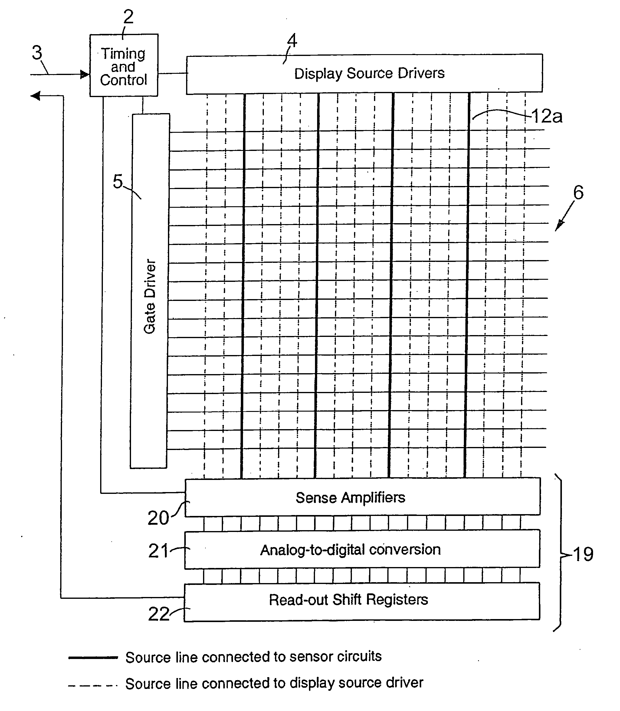
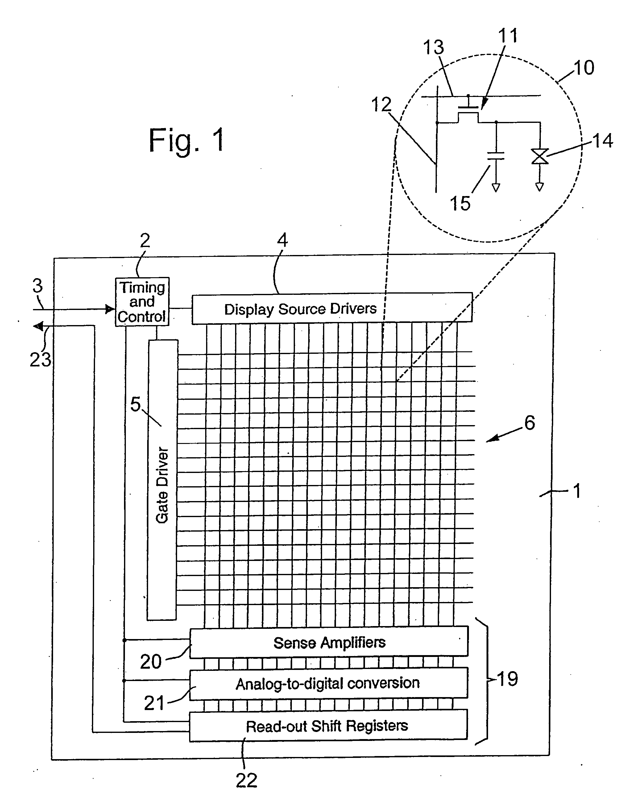
[0030] The active matrix liquid crystal display and sensor apparatus is formed on a display substrate illustrated diagrammatically at 1 and comprises a timing and control circuit 2 connected to an input 3 for receiving timing and control signals together with image data to be displayed. The circuit 2 supplies the appropriate signals to a data signal generator in the form of a display source driver 4 and a scan signal generator in the form of a gate driver 5. The drivers 4 and 5 may be of any suitable type, such as of a standard or conventional type, and will not be described further.

[0031] The display source driver 4 has a plurality of outputs which are connected to but isolatable from a plurality of matrix column electrodes which act as column data lines for the active matrix of picture elements (pixels) indicated at 6. The display source driver outputs may, for example, only be connected to the data lines when the driver is enabled by the control circuit 2. The column electrodes e...


PUM

PropertyMeasurementUnit
voltageaaaaaaaaaa
currentaaaaaaaaaa
capacitanceaaaaaaaaaa

Abstract

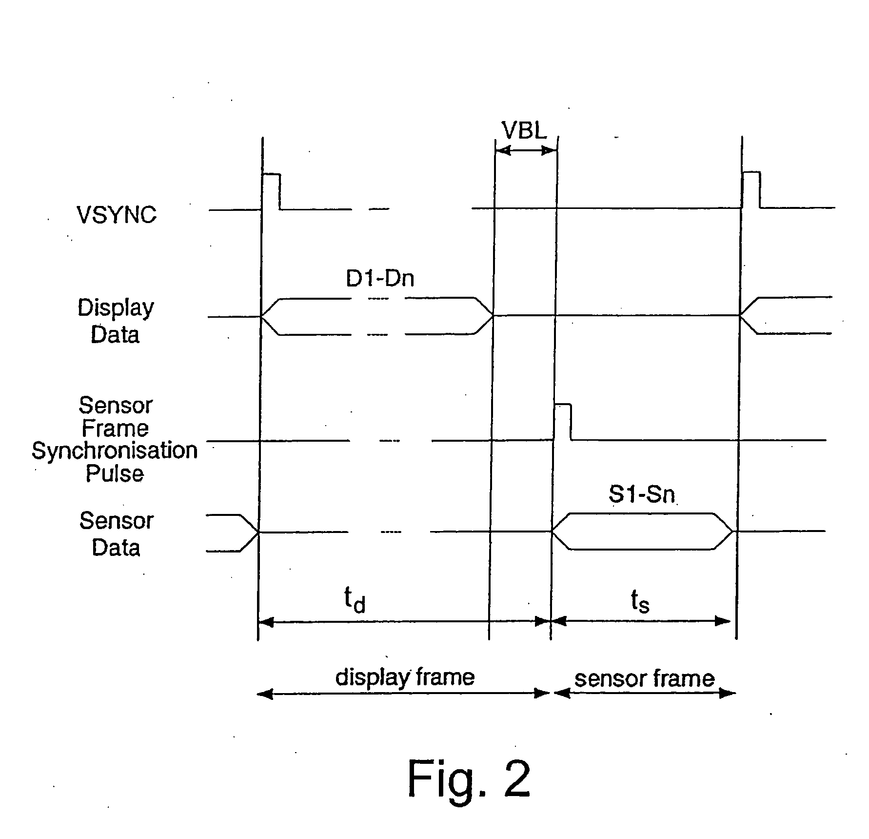
An apparatus is provided which integrates sensor functionality with an active matrix display such as an AMLCD. A conventional active matrix 6 of LCD pixels 10 is provided with standard display source and gate drivers 4 and 5. The display source driver 4 supplies data signals for generating the required pixel response to column electrodes 12 which are also connected to an output arrangement 19 including sense amplifiers 20. During a display phase of operation, the AMLCD operates conventionally with the matrix 6 being refreshed a row at a time and frame by frame. Between frames, the sense amplifiers 20 are enabled and the matrix 6 is again scanned by the gate driver 5. The characteristics of each pixel represent an external stimulus which is sensed by the relevant sense amplifier 20 and supplied at an output 23 of the arrangement.

Description

[0001] This Nonprovisional application claims priority under 35 U.S.C. .sctn.119(a) on Patent Application No. 0304587.9 filed in Great Britain on Feb. 28, 2003, the entire contents of which are hereby incorporated by reference.[0002] The present invention relates to an active matrix display and sensor apparatus.BACKGROUND TO THE INVENTION[0003] Active matrix liquid crystal displays (AMLCDs) may be used in products which require an input function. For example, mobile telephones and personal digital assistants (PDAs) may display information to a user on an AMLCD and require input from the user, for example from a telephone keypad. Alternatively or additionally, AMLCDs may be required to adjust automatically to environmental conditions, such as ambient light or temperature. In such cases, a sensor is required to accept an input from outside the apparatus. In known arrangements, such sensor functionality has been provided by adding extra components to the display. For example, in order ...

Claims


Application Information

Patent Timeline
Patent Type & Authority Applications(United States)
IPC IPC(8): G02F1/133G02F1/1362G06F3/033G06F3/041G09G3/20G09G3/36
CPCG02F1/13338G06F3/0412G02F1/13454G06F3/04166G06F3/0447B26D1/08B26D5/12B26D7/01
Inventor BROWN, CHRISTOPHER JAMES
Owner SHARP KK
Learn More