Method and apparatus for determining an optimal pumping rate based on a downhole dew point pressure determination

a technology of dew point pressure and pumping rate, which is applied in the field of spectrometry, can solve the problems of limited existing techniques for maintaining sample formation pressure, inconvenient pretension or compression springs, and reduced ability to evaluate the actual properties of formation fluid

Active Publication Date: 2004-11-25
BAKER HUGHES INC
View PDF4 Cites 55 Cited by
  • Summary
  • Abstract
  • Description
  • Claims
  • Application Information

AI Technical Summary

Problems solved by technology

Phase separation significantly changes the formation fluid characteristics, and reduces the ability to evaluate the actual properties of the formation fluid.
Existing techniques for maintaining the sample formation pressure are limited by many factors.
Pretension or compression springs are not suitable because the required compression forces require extremely large springs.
Shear mechanisms are inflexible and do not easily permit multiple sample gathering at different locations within the well bore.
Gas charges can lead to explosive decompression of seals and sample contamination.
Gas pressurization systems require complicated systems including tanks, valves and regulators which are expensiv...

Method used


Image

  • Method and apparatus for determining an optimal pumping rate based on a downhole dew point pressure determination
  • Method and apparatus for determining an optimal pumping rate based on a downhole dew point pressure determination
  • Method and apparatus for determining an optimal pumping rate based on a downhole dew point pressure determination

Examples


Embodiment Construction

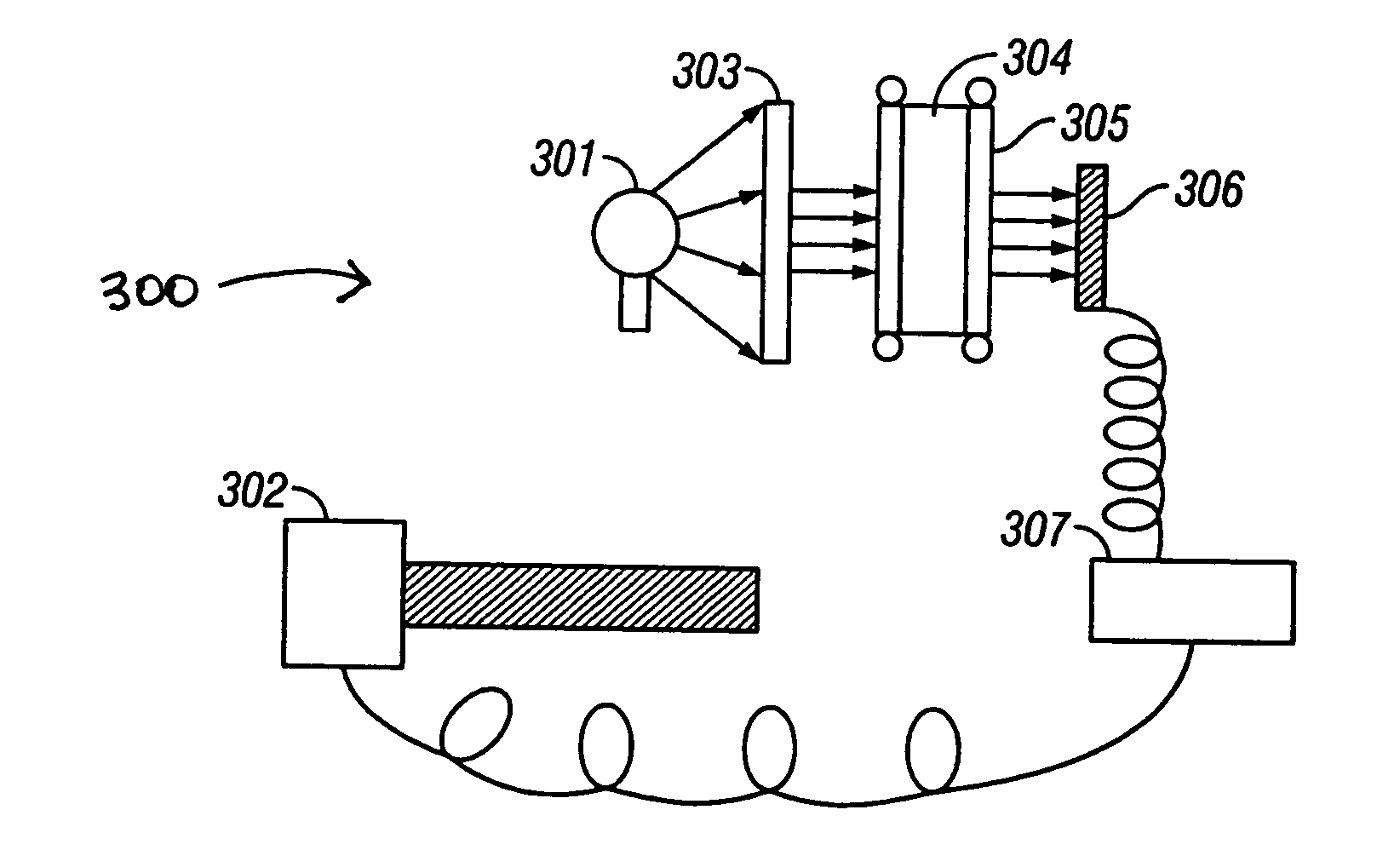
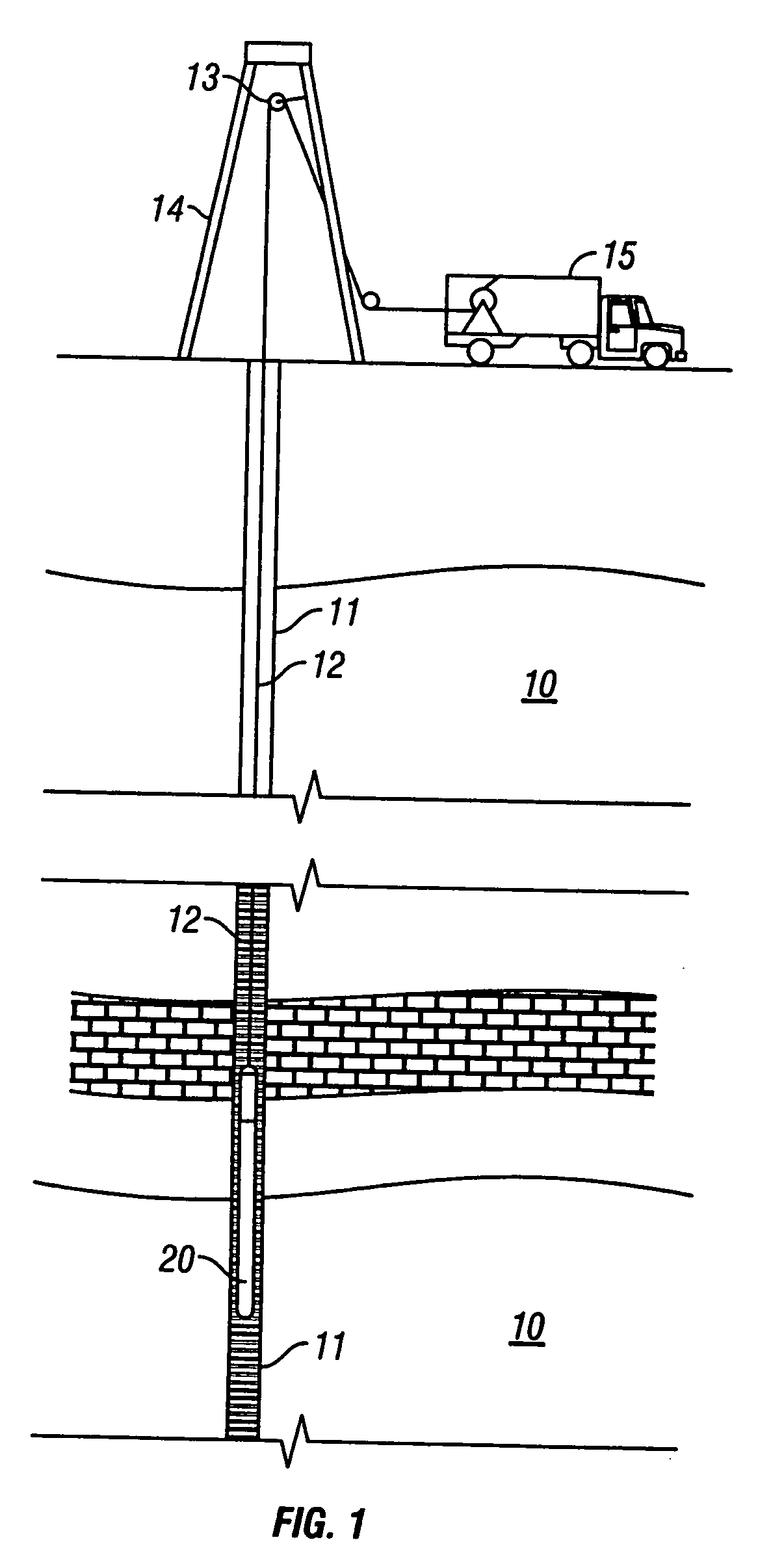
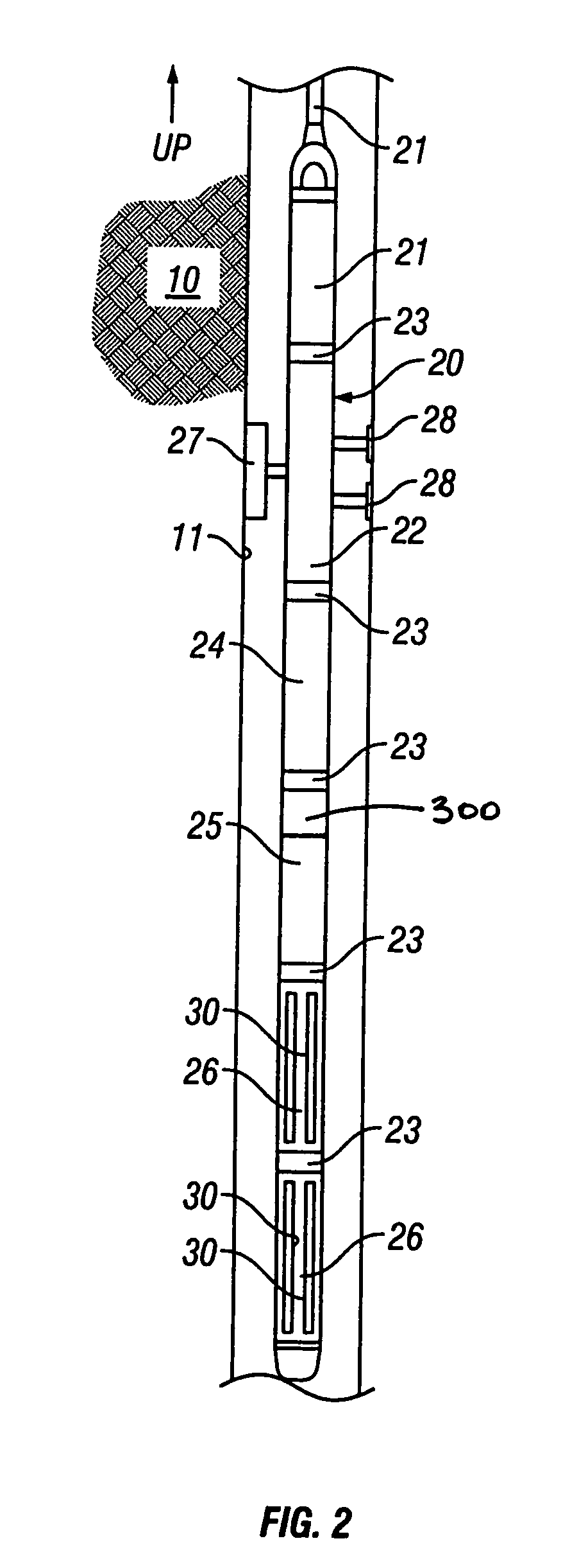
[0033] Baker Atlas provides the Reservoir Characterization Instrument.TM. (RCI.TM.) to evaluate samples representative of a hydrocarbon reservoir. The RCI.TM. is used to measure reservoir pressure as well as collecting samples from the reservoir. The samples are processed in pressure / volume / temperature (PVT) laboratories to determine the thermodynamic properties and relationships (PVT data) which are used to infer the properties of the formation from which a sample is taken. The quality of this data is directly dependent on the quality of the sample collected by the RCI.TM.. Some of the most difficult samples to collect are near critical hydrocarbons, retrograde gas, and wet gas. The dew point of the gas sample is a very important parameter in terms of the sample quality. If the sample is dropped below the dew point it could loose substantial amounts of liquid hydrocarbon in the reservoir or in the tool and hence severely alter its composition. One of the tools that is run in conjun...


PUM


Abstract

The present invention provides a down hole spectrometer for determination of dew point pressure to determine an associated optimal pumping rate during sampling to avoid precipitation of asphaltenes in a formation sample. A sample is captured at formation pressure in a controlled volume. The pressure in the controlled volume is reduced. Initially the formation fluid sample appears dark and allows less light energy to pass through a sample under test. The sample under test, however, becomes lighter and allows more light energy to pass through the sample as the pressure is reduced and the formation fluid sample becomes thinner or less dense under the reduced pressure. At the dew point pressure, however, the sample begins to darken and allows less light energy to pass through it as apshaltenes begin to precipitate out of the sample. Thus, the dew point is that pressure at which peak light energy passes through the sample. The dew point pressure is plugged into an equation to determine the optimum pumping rate for a known mobility, during sampling to avoid dropping the pressure down to the dew point pressure to avoid asphaltene precipitation or dew forming in the sample. The bubble point can be plugged into an equation to determine the optimum pumping rate for a known mobility, during sampling to avoid dropping the pressure down to the bubble point pressure to avoid bubbles forming in the sample.

Description

[0001] This patent application claims priority from U.S. provisional patent application No. 60 / 472,358 filed on May 21, 2003 entitled "A Method and Apparatus for Downhole Dew Point Determination" by M. Shammai, which is hereby incorporated by reference in its entirety.[0002] 1. Field of the Invention[0003] The invention relates to spectrometry in a down hole well bore environment and specifically, it pertains to a robust apparatus and method for determining an optimal pumping rate based on a in situ downhole dew point pressure or bubble point pressure either known or determined by measuring light spectra for electromagnetic absorbance for a formation fluid sample while decreasing the pressure on the sample under test.[0004] 2. Summary of the Related Art[0005] Earth formation fluids present in a hydrocarbon producing well typically comprise a mixture of oil, gas, and water. The pressure, temperature and volume of formation fluids control the phase relation of these constituents. In a...

Claims


Application Information

Patent Timeline
IPC IPC(8): E21B49/10
CPCE21B49/10
Inventor SHAMMAI, MICHAEL
Owner BAKER HUGHES INC
Why Eureka
Try Eureka