
Method for avoiding air pockets in a joint between two structural components

a technology of structural components and air pockets, applied in the field of carbon fiber reinforced composite materials, can solve the problems of undesirable joint gaps or air pockets, excessive shim mass, and excessive removal of excess, so as to reduce dimensions, avoid excess filler material application, and small air pockets

Inactive Publication Date: 2004-11-25
AIRBUS OPERATIONS GMBH
View PDF10 Cites 43 Cited by
  • Summary
  • Abstract
  • Description
  • Claims
  • Application Information

AI Technical Summary

Benefits of technology

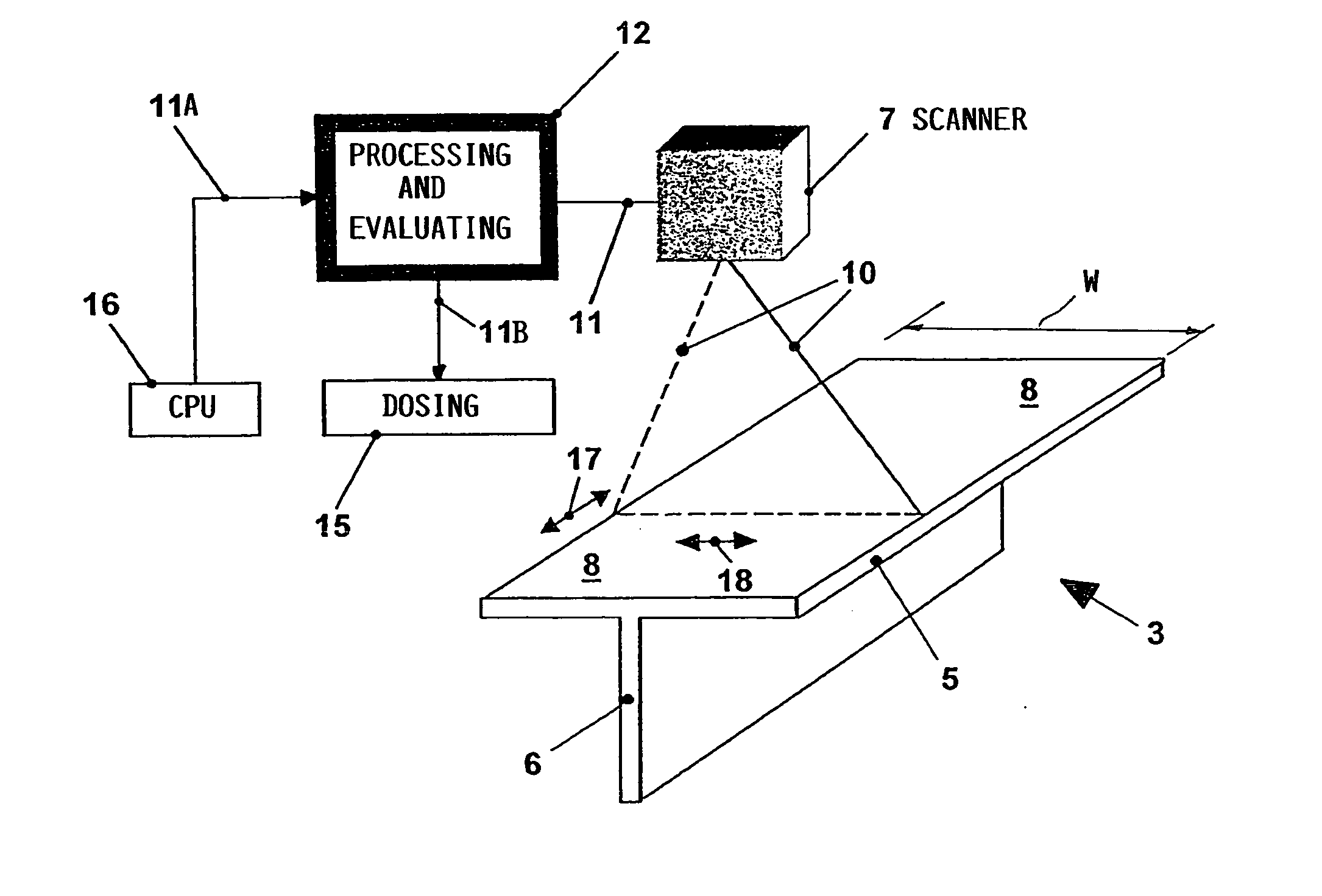
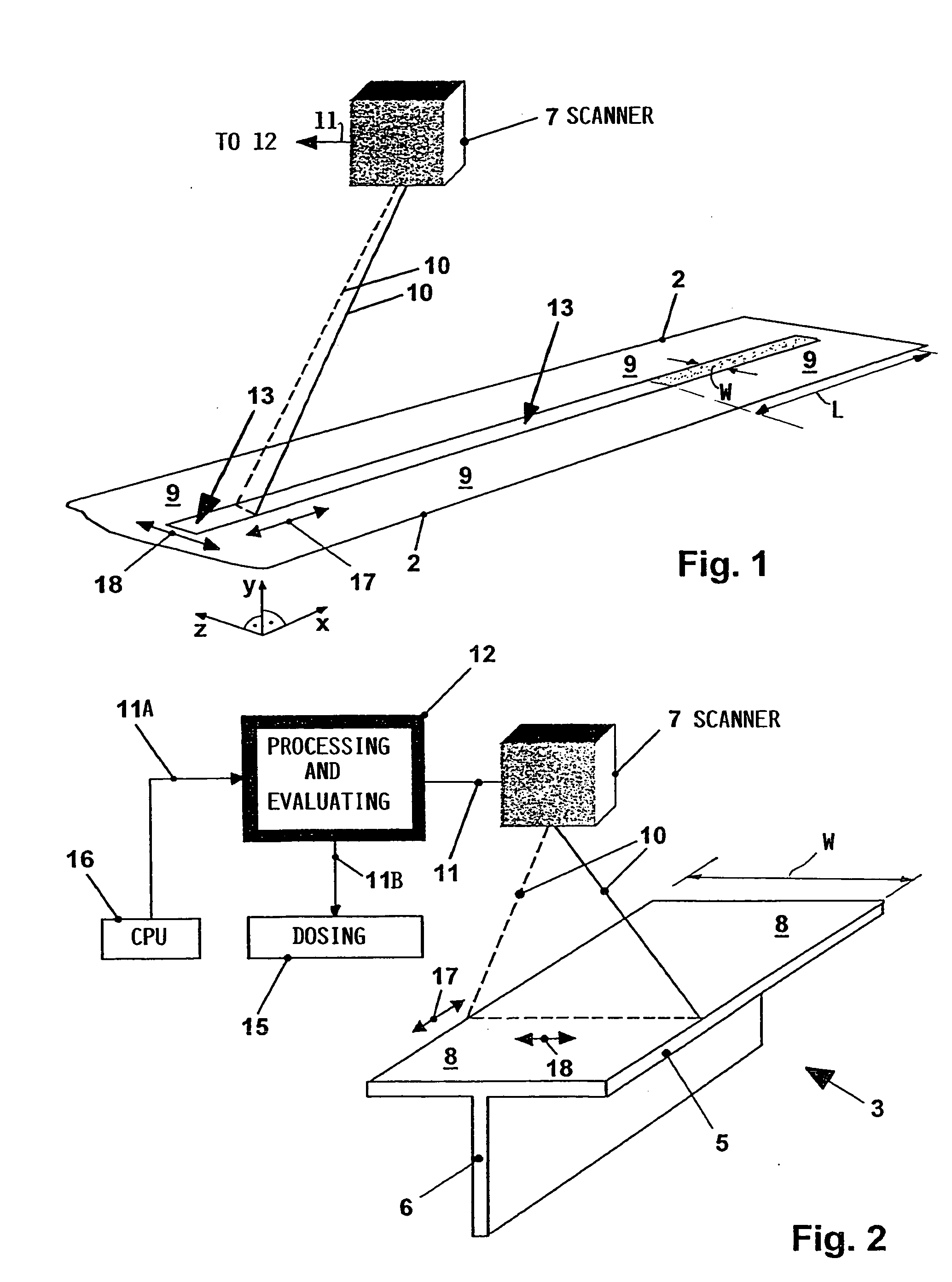
[0007] to precisely fill any joining gaps or rather joining gap portions between or on joining surface areas of structural components with due regard to the individual topographies of the surface areas to be joined to thereby avoid air pockets in the joints;
[0009] to avoid excessive filling of the volume of gap portions regardless of the gap configurations and dimensions also referred to as gap topographies;
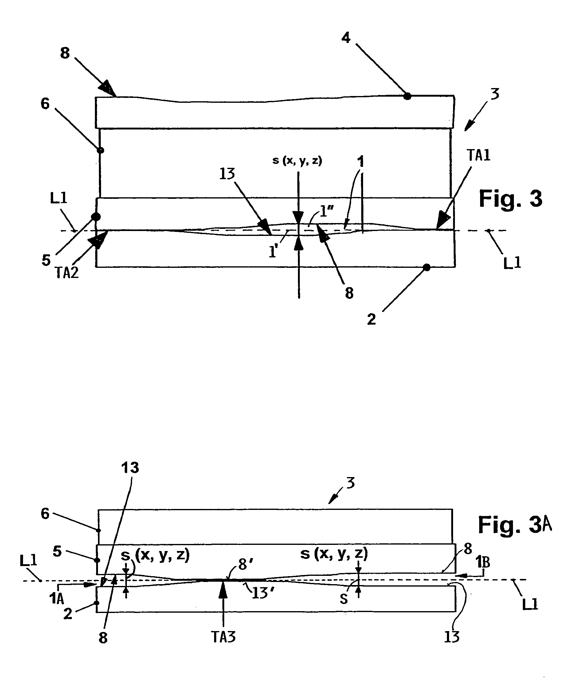
[0021] When the smoothing out steps are completed the joint is formed by joining said first and second structural components to each other whereby said gap filler material fills completely, said joining gap to prevent the formation of air inclusions in the joint.

Problems solved by technology

The skin surface areas and the stringer surface areas to be joined are not uniformly smooth or level so that joining gaps or air pockets occur.
These joining gaps or air pockets are undesirable since they reduce the mechanical strength of the joint.
However, such maximal gap dimension is not always achieved in the manufacture of the individual stringers and skin sections.
As a result, it is possible to apply too much shim mass and the excess must be removed which is rather cost intensive and time consuming.
Conventionally, it is difficult to determine the exact quantity of the required shim mass because the gap depth is not uniform throughout the gap area.
Preparing the joining surfaces, for example by the fine grinding or polishing so that these surfaces are completely or at least substantially plane and do not form any gap, is cost intensive and time consuming.
Furthermore, the above conventional joining methods are not suitable for connecting relatively thick walled components to each other such as skin sections and stringers made of carbon fiber reinforced composite materials.
Rigid components if pressed to each other do not allow for minimizing the gap dimensions due to their rigidity.

Method used


Image

  • Method for avoiding air pockets in a joint between two structural components
  • Method for avoiding air pockets in a joint between two structural components
  • Method for avoiding air pockets in a joint between two structural components

Examples


Embodiment Construction

[0033] FIG. 1 shows perspectively a first structural component such as a skin or shell section 2 having a relatively thick wall with an inwardly facing surface 9. A portion of the inwardly facing surface 9 of the skin section 2 forms a first joining surface area 13 that will be joined or bonded by an adhesive to a second joining surface area 8 of a second structural component 3 such as a stringer 3 to be described in more detail below. In practice the first and second joining surface areas 13 and 8 are not exactly plane due to acceptable manufacturing tolerances. Thus, it is the purpose of the invention to provide a method to level out or smooth out any topographic irregularities in the surface areas 13 and 8 to avoid the formation of air pockets in the finished joint.

[0034] Without such smoothing or leveling air pockets of various geometric configurations could be formed and it is the purpose of the invention to avoid such faulty gap formations. For this purpose the topography of t...


PUM

PropertyMeasurementUnit
Currentaaaaaaaaaa
Currentaaaaaaaaaa
Digital informationaaaaaaaaaa

Abstract

When two structural components are to be joined, for example, when an aircraft skin section is to be secured to a stringer by an adhesive bonding, it is important that the joining surface areas are plane to avoid the formation of air inclusions in the joint because air inclusions weaken the mechanical strength of the joint. Thus, a surface topography that is not plane must be smoothed out prior to the joining. For this purpose the surface areas to be joined are optically scanned to provide topographical information for each surface area that needs to be smoothed out for providing a plane joining surface. The topographical information is processed to ascertain the configuration and volume of the surface topography that needs to be filled with a filler material to produce a plane surface or at least a smooth surface without hills and dales. A respective control signal is produced and fed to a dosing equipment which supplies the exact volume of filler material required for planing or smoothing the surface topography. When smoothing is completed the two components are ready for joining for example by the application of pressure and heat to the filler material.

Description

PRIORITY CLAIM[0001] This application is based on and claims the priority under 35 U.S.C. .sctn.119 of German Patent Application 103 19 926.8, filed on May 2, 2003, the entire disclosure of which is incorporated herein by reference.[0002] The invention relates to a method for precisely filling or leveling joining surfaces that form a joint between two structural components such as a body skin and a stringer in an aircraft body, whereby air pockets in the joint are avoided.BACKGROUND INFORMATION[0003] Fiber reinforced composite materials particularly carbon fiber reinforced composite materials are used in aircraft construction. Conventionally thin stringers and thin skin sections made of these carbon fiber reinforced materials are used, for example in passenger aircraft of the "Airbus" (Tradename) type. Stringers and skin sections are interconnected by adhesive bonding or riveting. The skin surface areas and the stringer surface areas to be joined are not uniformly smooth or level so...

Claims


Application Information

Patent Timeline
IPC IPC(8): B29C65/00B29C65/52B64F5/00
CPCB29C65/52B29C65/48B29C66/721B29K2307/00B29L2031/3076B29C65/5057B29C65/5078B29C66/112B29C66/1122B29C66/131B29C66/524B29C66/532B29C66/967B29C65/4835B29C66/02B29C66/7212B29C66/61B29K2307/04B29K2309/08
Inventor WEISSER, TILMANN
Owner AIRBUS OPERATIONS GMBH
Learn More