Exhaust gas purifying device and method for internal combustion engine

a technology of exhaust gas purification device and internal combustion engine, which is applied in the direction of machines/engines, electric control, separation processes, etc., can solve the problems of exhaust gas below, nox catalyst becomes saturated and cannot absorb nox, and it is difficult to raise the bed temperature of nox catalyst to the temperature required for the recovery from sulfur poisoning

Inactive Publication Date: 2004-12-30
TOYOTA JIDOSHA KK
View PDF6 Cites 30 Cited by
  • Summary
  • Abstract
  • Description
  • Claims
  • Application Information

AI Technical Summary

Problems solved by technology

Thus, if a predetermined amount or more of sulfur oxides (SOx) is accumulated, the NOx catalyst becomes saturated and unable to absorb NOx.
However, exhaust gas is below the aforementioned temperature during lean-bum operation.
Thus, when the engine is in a normal operational state, it is difficult to raise the bed temperature of the NOx catalyst to a temperature required for the recovery from sulfur poisoning.
However, if the PMs collected by the filter are accumulated on the filter, the filter may be clogged with the PMs.
Such clogging raises the pressure of the exhaust gas upstream of the filter, thereby possibly causing reduced output power of the internal combustion engine and damage of the filter.
However, since the exhaust gas temperature of the diesel engine is lower than this temperature, it is difficult to remove the PMs through combustion in a normal operation state.
However, this requires a great amount of energy to be supplied from the outside.
However, if the reducing agent is added during high-load operation of the internal combustion engine, the reducing agent bums in the occlusion/reduction-typ-e NOx catalyst.
As a result, the temperature of the occlusion/redu

Method used


Image

  • Exhaust gas purifying device and method for internal combustion engine
  • Exhaust gas purifying device and method for internal combustion engine
  • Exhaust gas purifying device and method for internal combustion engine

Examples


Embodiment Construction

[0038] In the following description and the accompanying drawings, the invention will be described in more detail in terms of exemplary embodiments.

[0039] Hereinafter, a specific embodiment of an exhaust gas purifying device for an internal combustion engine according to the invention will be described with reference to the drawings. The following description deals with an exemplary case where the exhaust gas purifying device for the internal combustion engine according to the invention is applied to a diesel engine for driving a vehicle.

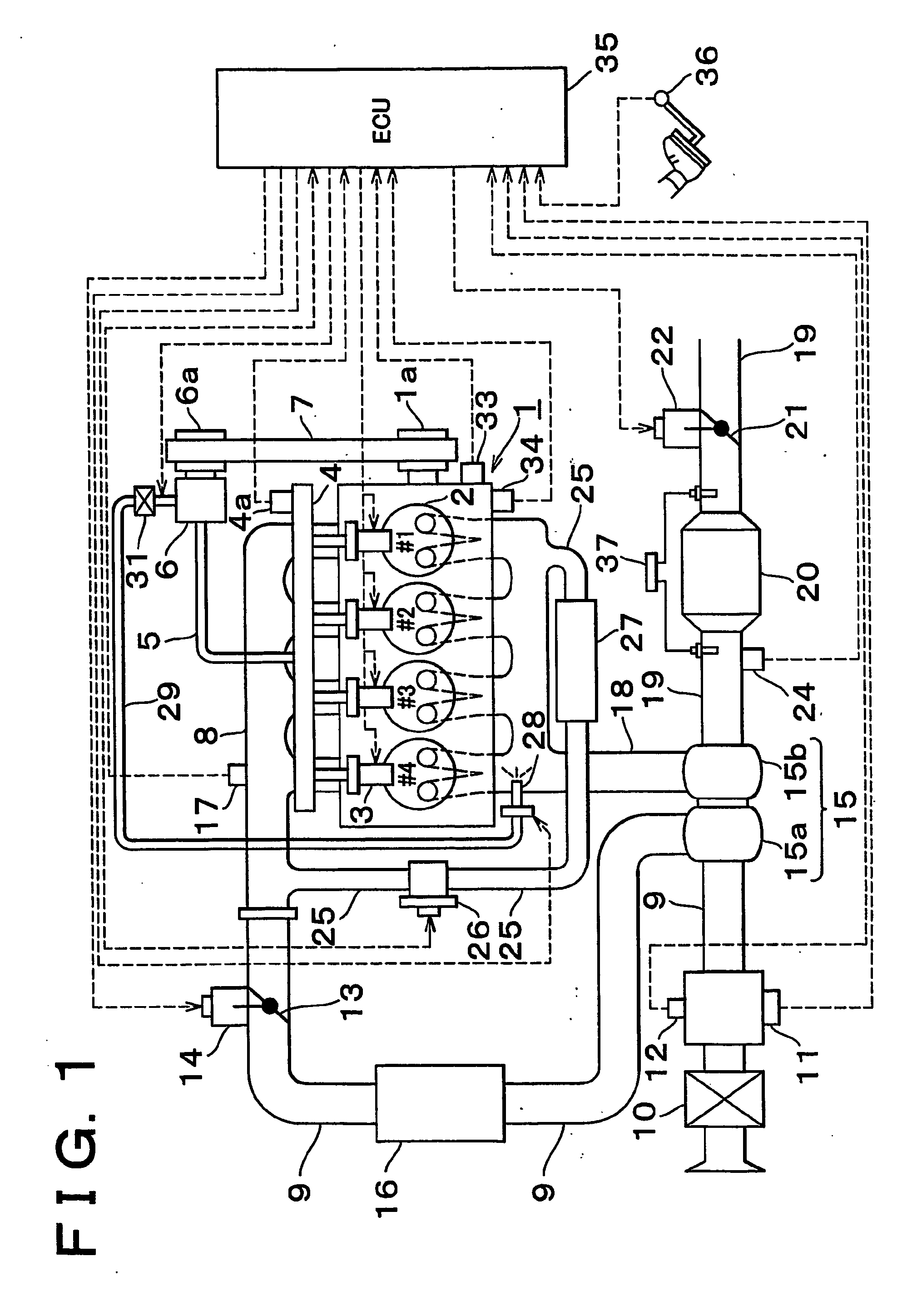
[0040] FIG. 1 schematically shows the structure of an internal combustion engine 1 which has intake and exhaust systems and to which the exhaust gas purifying device according to this embodiment is applied.

[0041] The internal combustion engine 1 shown in FIG. 1 is a water-cooled four-cycle diesel engine having four cylinders 2.

[0042] The internal combustion engine 1 has fuel injection valves 3 each injecting fuel directly into a combustion chamber o...


PUM

PropertyMeasurementUnit
Temperatureaaaaaaaaaa
Concentrationaaaaaaaaaa
Ratioaaaaaaaaaa

Abstract

Removal of fine particles by oxidation or/and sulfur poisoning recovery control may be required when an internal combustion engine has been in an extremely low load state for a predetermined period or more. In this case, the engine speed of the internal combustion engine (1) is adjusted to a range where the temperature of a filter (20) can be raised by heat-up control. The heat-up control is then executed by a filter temperature control means to raise the temperature of the filter (20) to a predetermined value. When the filter (20) reaches the predetermined temperature by means of low-temperature combustion, post-injection, VIGOM-injection, addition of 10 fuel to an exhaust system and the like, removal of fine particles by oxidation or/and sulfur poisoning recovery control for eliminating sulfur poisoning of a NOx absorbent are conducted. Removal of PMs captured by the filter and sulfur poisoning recovery control of the NOx absorbent can thus be conducted even if the internal combustion engine is left in an extremely low load operational state.

Description

[0001] 1. Field of the Invention[0002] The invention relates to an exhaust gas purifying device and method for an internal combustion engine, and more particularly, to an exhaust gas purifying device and an exhaust gas purifying method which are capable of conducting recovery from sulfur poisoning and the like even if extremely low-load operation is continued.[0003] 2. Description of Related Art[0004] In an internal combustion engine installed in an automobile or the like, especially in a diesel engine or a lean-bum gasoline engine in which a mixture containing an excessive amount of oxygen (a mixture exhibiting a so-called lean air-fuel ratio) can burn, the advent of an technology for purifying nitrogen oxides (NOx) contained in exhaust gas in the internal combustion engine has been expected.[0005] A technology of disposing an NOx absorbent in an exhaust system of an internal combustion engine has been proposed to meet such a demand. An occlusion / reduction-type NOx catalyst has bee...

Claims


Application Information

Patent Timeline
IPC IPC(8): F02D43/00B01D46/42B01D53/86B01D53/94F01N3/02F01N3/022F01N3/023F01N3/025F01N3/08F01N3/20F01N3/24F01N3/28F02B37/00F02D41/02F02D41/04F02D41/08F02D41/40F02D45/00F02M25/07
CPCF01N3/0222F01N3/023F01N3/0253F01N3/0821F01N3/0842F01N3/0871F01N3/0885F01N2260/14F01N2570/04F02B37/00F02D41/025F02D41/028F02D41/029F02D41/08F02D41/405F02M25/0707F02M25/0713F02M25/0731F02M25/0738F02M25/0772Y02T10/44Y02T10/26F02M26/05F02M26/10F02M26/28F02M26/33F02M26/53Y02T10/12Y02T10/40F02D41/04
Inventor OHKL, HISASHIKOBAYASHI, MASAAKIMAGARIDA, NAOFUMISHIBATA, DAISUKEISHIYAMA, SHINOBUNEGAMI, AKIHIKO
Owner TOYOTA JIDOSHA KK
Why Eureka
Try Eureka