Eureka AIR delivers breakthrough ideas for toughest innovation challenges, trusted by R&D personnel around the world.

High purity silica crucible by electrolytic refining, and its production method and pulling method

a technology of electrolytic refining and high purity, applied in the direction of crystal growth process, manufacturing tools, under a protective fluid, etc., can solve the problems of easy deformation or buckled whole crucible made with synthetic silica glass, and the quality of single silicon crystals is affected

Active Publication Date: 2005-01-06
JAPAN SUPER QUARTZ CORP
View PDF6 Cites 20 Cited by
  • Summary
  • Abstract
  • Description
  • Claims
  • Application Information

AI Technical Summary

Benefits of technology

[0058] According to said production method of the present invention, it is possible to give the silica glass crucible, in which each content of Na and Li being contained in the area of depth 1 mm from the inside surface are less than 0.05 ppm, preferably less than 0.01 ppm. Moreover, as for the silica glass crucible being shown in Example, each concentration of K and Fe are reduced to less than 0.05 ppm other than Na and Li, and the concentration of Cu is reduced to less than 0.01 ppm. This crucible is suitable as the silica glass crucible for pulling the single silicon crystal. EXAMPLE
[0059] Hereinafter, the present invention will be explained with Example and Comparison example. Examples 1 and 2
[0060] The silica glass crucible is produced by using the raw material powder of natural silica being shown in Table 1, and applying the voltage under the conditions of from Table 2 to Table 5. These results are shown in from Table 2 to Table 5(

Problems solved by technology

Moreover, in the case of using for the silica glass crucible for pulling the single silicon crystal, there is a problem that the quality of the single silicon crystal is affected with the impurities, such as alkali metals etc., being contained in the crucible.
However, since the temperature and using time of the crucible at the time of pulling are under a severe condition by the enlargement of the pulled single crystal, there are new problems that the alkali metals etc. being contained in the natural silica glass layer in the outside of the crucible is diffused to the synthetic silica glass layer in the inner and dissolved to silicon melt, to give bad effects to the quality of the single silicon crystal.
On the other hand, when the whole of the crucible is made with the high purity synthetic silica glass, the problem about the impurity diffusion is solved, but in the present condition, since the synthetic silica glass has very lower viscosity than that of the natural silica, the whole of the crucible made with the synthetic silica glass is deformed or buckled easily, so that said crucible can not be used for long time.
Moreover, for requiring the high performance silica glass crucible, it has been in the tendency that the temperature for melting the glass becomes high.
As the result, there are problems that the impurity is concentrated on the inside surface of the crucible by the vaporization of SiO, and the impurities, such as alkali metals etc., is diffused from the natural layer in the outside of the crucible to the high purity synthetic layer in the inside of crucible during the arc melting, as described above.
When HF etching is carried out to remove such impurities being contained in the inside surface of the crucible, it takes time very much, and in addition, an irregularity, which is said to as HF cracks in general, is generated on the surface by the HF washing for long time, so that the yield of the single crystal becomes to be decreased on the contrary.
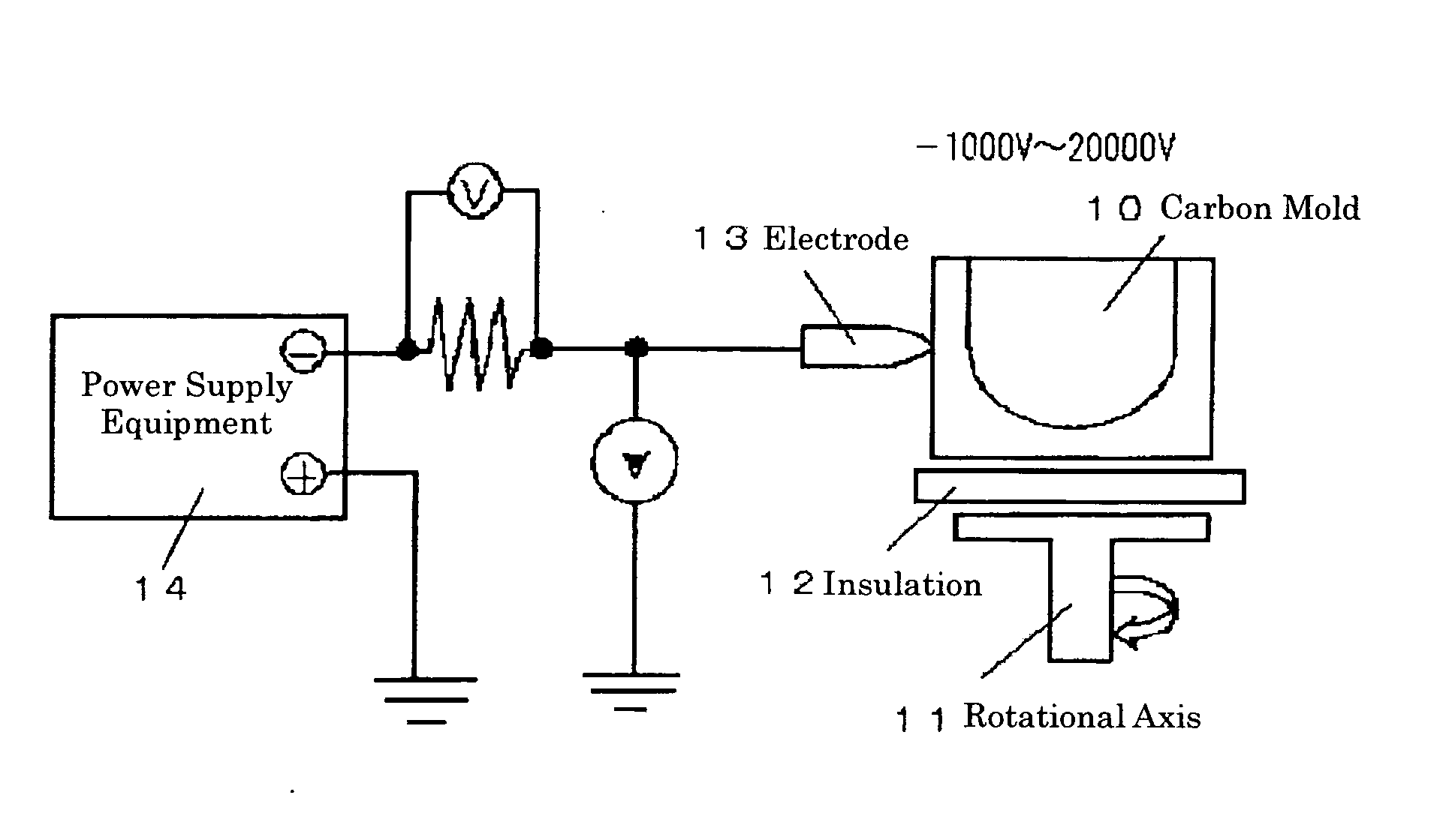
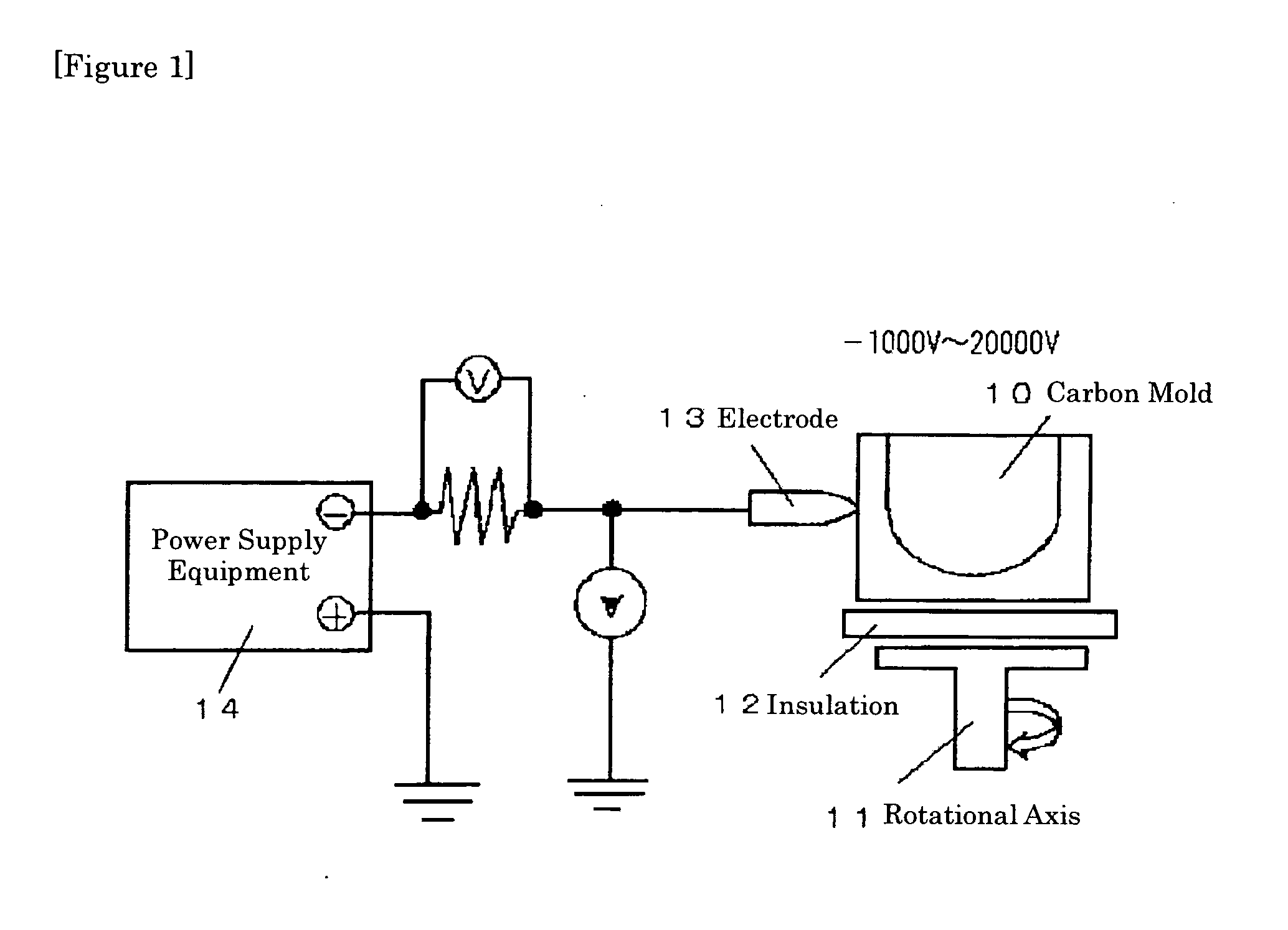
However, since a plasma atmosphere is occurred during an arc discharge at the time of producing the crucible, the discharge is generated violently around an electrode when the electrode is charged in positive.
In addition, from the reason, such as the insulation between the arc plasma and the mold is not sufficiently, it is difficult to carry out the electrolytic refining sufficiently.
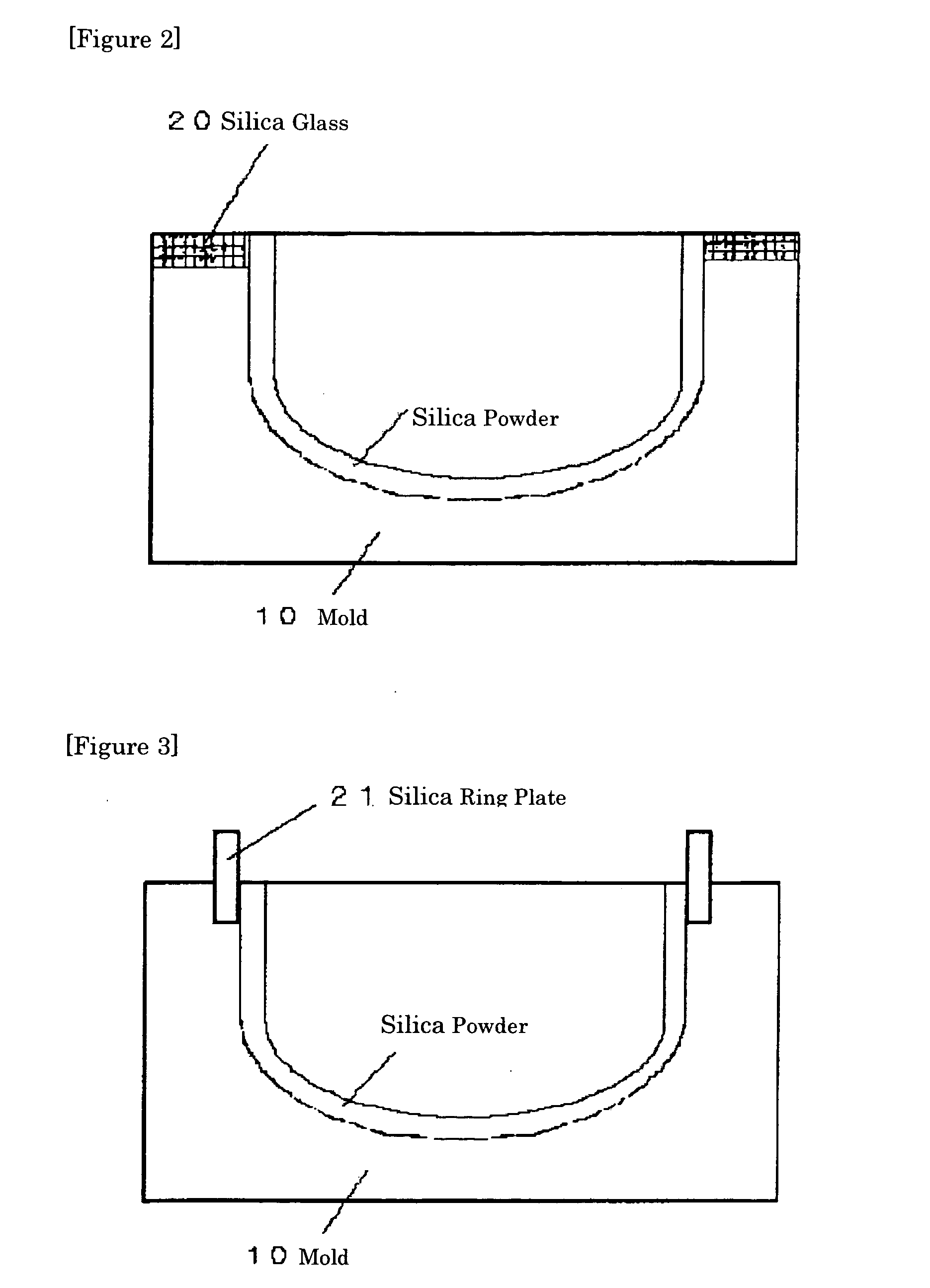
By the way, in the case that the silica powder is filled in the mold to be heated and melted to make the crucible, since the upper end of the mold and the upper end of the crucible are the same height, it is difficult to take an electrical isolation between the arc plasma and the mold in this configuration.
However, all of these methods in the above examples are aimed at the crucible being formed already, so that they are not the electrolytic refining during the arc melting.
Moreover, the method for applying the voltage between the crucible and the positive or negative electrode is not described in said conventional methods.
However, in the method, in which the crucible formed body is contacted with the positive or negative electrode and applied by the voltage, it is difficult to carry out electrolysis because of the following reasons.
(A) When the metal plate is used as the contact electrode, the impurity contamination is caused to decrease the quality and the dislocation free ratio of the single silicon crystal.
At this time, in order to carry out the economical electrolysis, it is necessary to apply the voltage at least 30000 V, and it is very difficult technically to insulate such a high voltage at the high temperature.

Method used


Image

  • High purity silica crucible by electrolytic refining, and its production method and pulling method
  • High purity silica crucible by electrolytic refining, and its production method and pulling method
  • High purity silica crucible by electrolytic refining, and its production method and pulling method

Examples


example

[0059] Hereinafter, the present invention will be explained with Example and Comparison example.

examples 1 and 2

[0060] The silica glass crucible is produced by using the raw material powder of natural silica being shown in Table 1, and applying the voltage under the conditions of from Table 2 to Table 5. These results are shown in from Table 2 to Table 5(Example 1).

[0061] The silica glass crucible is produced by using the raw material powder of natural silica being shown in Table 6, and applying the voltage under the conditions of from Table 7 to Table 10. These results are shown in from Table 6 to Table 10(Example 2).

TABLE 1ppmNaLiKCuFeRaw Material0.230.250.220.150.22Powder

[0062]

TABLE 2Thickness ofUn-meltedMeltingElectricityArea of less than 1 mm DislocationSilicaTemperatureResistanceAmountFrom Inside Surfacefree ratioPowder (mm)(° C.)(Ω)(C / m2)NaLiKCuFe(%)Example 1A0.5220050000150.020.0285Example 2A2220050000150.030.0384Comparison3220050000150.330.270.270.210.2452Example 1AComparison5220050000150.330.310.360.260.3547Example 2A

(Notice) Resistance is sum of a resistance of an un-melted sili...


PUM

PropertyMeasurementUnit
thicknessaaaaaaaaaa
thicknessaaaaaaaaaa
voltageaaaaaaaaaa

Abstract

This invention provides a high purity silica crucible having low impurity concentration in its inner portion, and its production method. The crucible, in which at least each content of Na and Li being contained in the depth of 1 mm from the inside surface is less than 0.05 ppm, is given by a production method of a high purity silica glass crucible, wherein a purity of the melted silica powder layer is increased by applying a voltage between a mold and an arc electrode to move impurity metals being contained in the melted silica glass layer to the outside, when the silica crucible is produced by arc plasma heating a raw material powder of silica in an inside surface of a hollow rotary mold. The method comprises, keeping an arc electrode potential of within ±500 V during an arc melting, applying a voltage of from −1000 V to −20000 V to a mold being insulated to the ground, and applying a high voltage to the un-melted silica powder layer of the outside.

Description

BACKGROUND OF THE INVENTION [0001] 1. Field of the Invention [0002] The present invention relates to a silica glass crucible having high purity in its inner portion, and its production method, wherein said silica glass crucible is used for pulling a single silicon crystal being used to a semiconductor etc. from the melted silicon. In addition, the present invention also relates to a pulling method using said silica glass crucible. [0003] 2. Discussion of the Prior Art [0004] A little amount of alkali metals has been contained in natural silica. When the silica glass containing said alkali metals is used as a heat treating substance for semiconductor industries etc., the substance is deformed or devitrified easily. Moreover, in the case of using for the silica glass crucible for pulling the single silicon crystal, there is a problem that the quality of the single silicon crystal is affected with the impurities, such as alkali metals etc., being contained in the crucible. [0005] As me...

Claims


Application Information

Patent Timeline
Patent Type & Authority Applications(United States)
IPC IPC(8): C03B19/09C30B15/00C30B15/10C30B29/06C03B20/00
CPCC03B19/095C03B2201/03C03C3/06Y10T117/1032C30B29/06Y10S117/90Y10T117/1052C30B15/10E03D5/006E03D1/003E03C1/01
Inventor KISHI, HIROSHIFUKUI, MASANORITSUJI, YOSHIYUKI
Owner JAPAN SUPER QUARTZ CORP
Why Eureka
Eureka Blog
Learn More