Control system for internal combustion engine

a control system and internal combustion engine technology, applied in the direction of electric control, valve drive, speed sensing governor, etc., can solve the problems of increasing the set value of the retardation amount of ignition timing, reducing the startability and increase the exhaust emissions, and unable to achieve excellent exhaust emissions reduction, etc., to achieve rapid activation, reduce exhaust emissions, and reduce the effect of exhaust emissions

Inactive Publication Date: 2005-01-06
HONDA MOTOR CO LTD
View PDF5 Cites 35 Cited by
  • Summary
  • Abstract
  • Description
  • Claims
  • Application Information

AI Technical Summary

Benefits of technology

ne, it possible to obtain the same advantageous effects as provided in the preferred embodiment of the control system according to the first aspect of the invention, which corresponds to claim 2.
In the control systems according to the first and second aspects of the invention, it is preferred that the engine has a catalytic converter provided in an exhaust passage, for reducing emissions of exhaust gases, and that the control system further comprises catalyst warmup-determining means for determining whether or not catalyst warmup control should be carried out after a start of the engine, for activation of the catalytic converter, and the exhaust valve timing-setting means sets the valve-opening timing of the exhaust valve to advanced timing with respect to the predetermined timing, when it is determined by the catalyst warmup-determining means that the catalyst warmup control should be carried out.
With the arrangement of this preferred embodiment, when it is determined that the catalyst warmup control should be carried out for the engine, the valve-opening timing of the exhaust valves is set to advanced timing with respect to the predetermined timing in which the compression ratio becomes equal to the expansion ratio in the combustion cycle of the engine, so that high-temperature exhaust gases during the combustion stroke can be supplied to the catalytic converter to thereby more rapidly activate the catalytic converter, which contributes to further reduction of exhaust emissions after the start of the engine.
To attain

Problems solved by technology

Therefore, when the intake temperature or the engine temperature is low, the lowering of the temperature within the cylinder caused by adiabatic expansion of the mixture within the cylinder can cause liquidation of fuel, resulting in degraded startability and increased exhaust emissions.
However, the effects of reduction of exhaust emissions by this control are limited, and

Method used


Image

  • Control system for internal combustion engine
  • Control system for internal combustion engine
  • Control system for internal combustion engine

Examples


Embodiment Construction

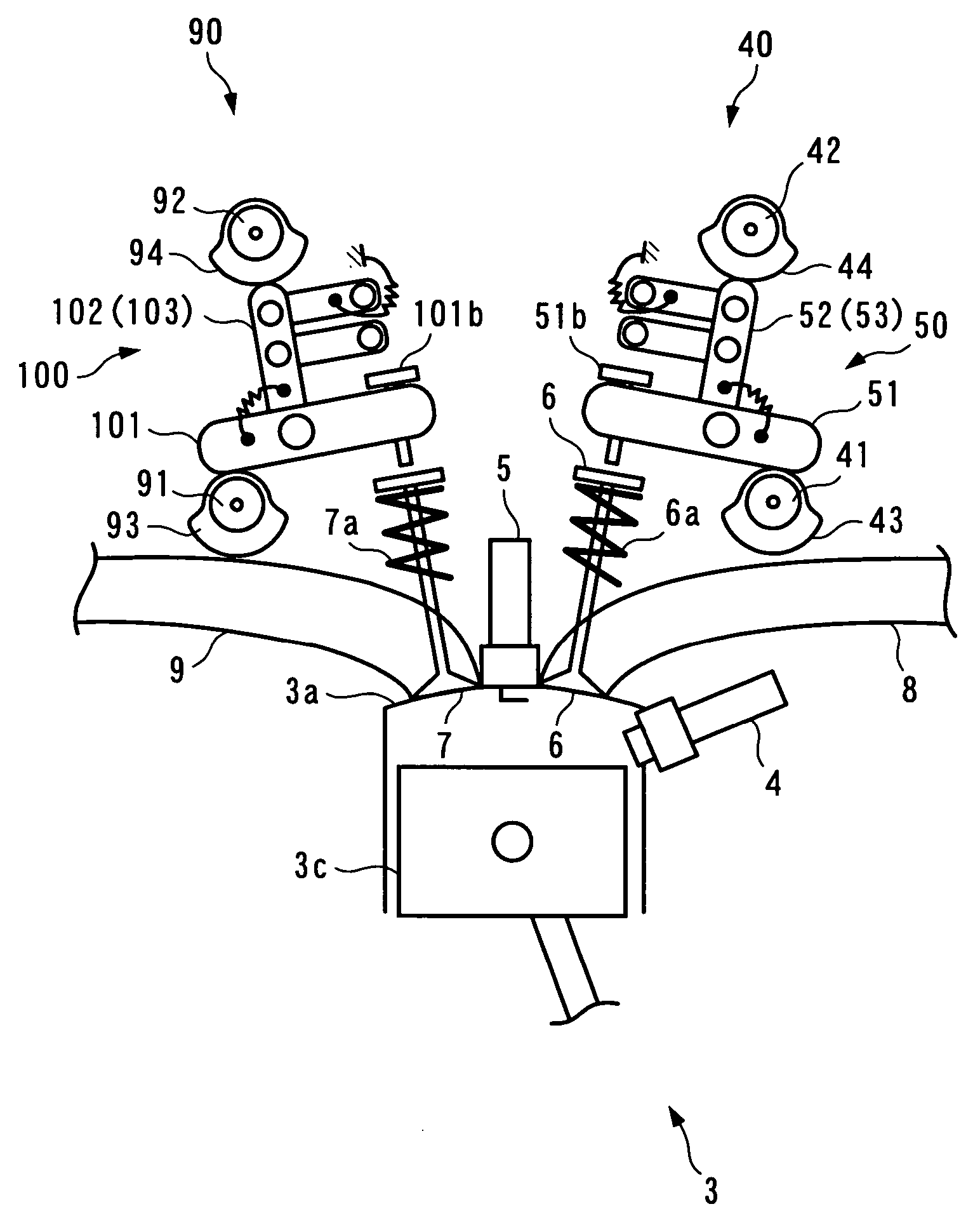
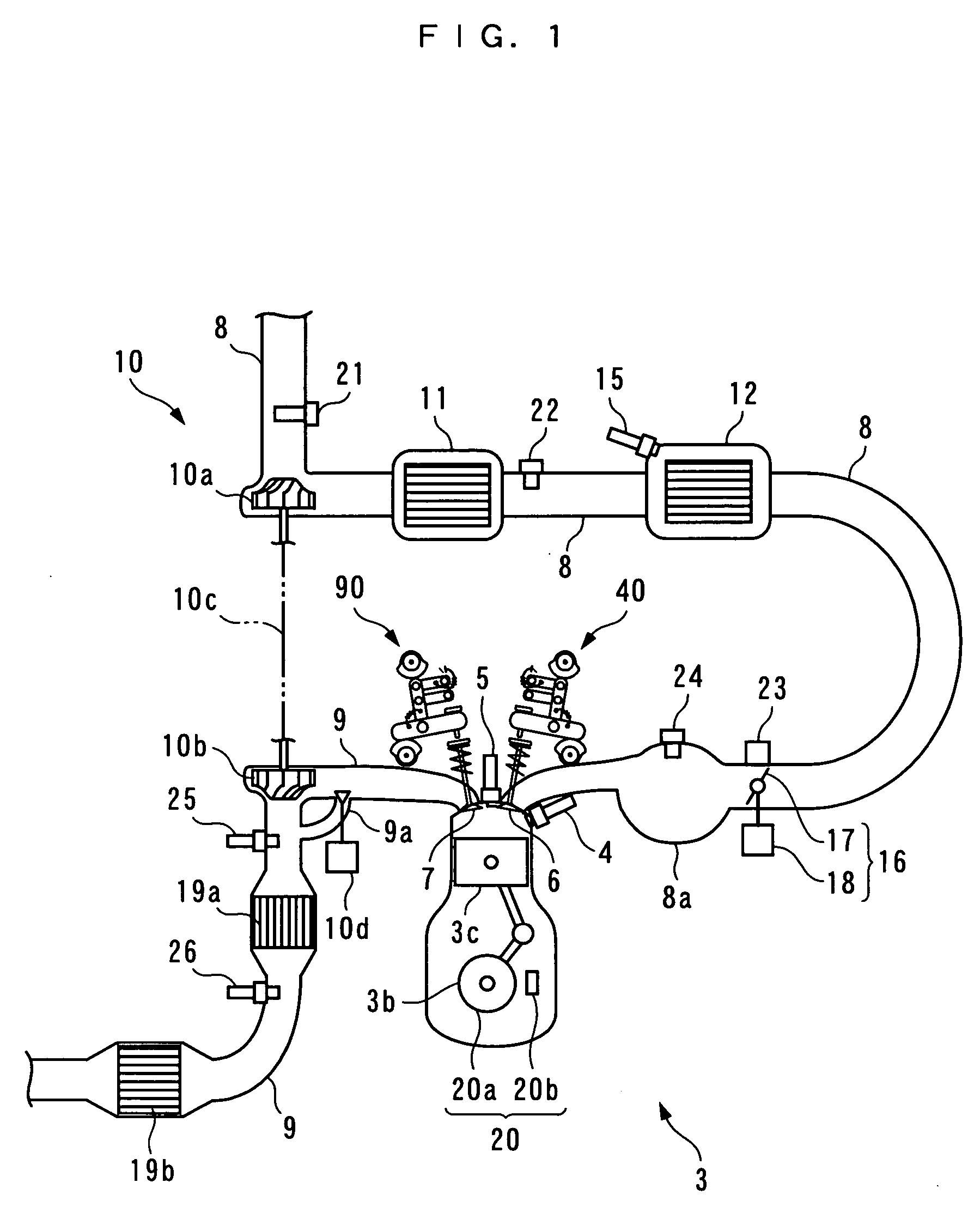
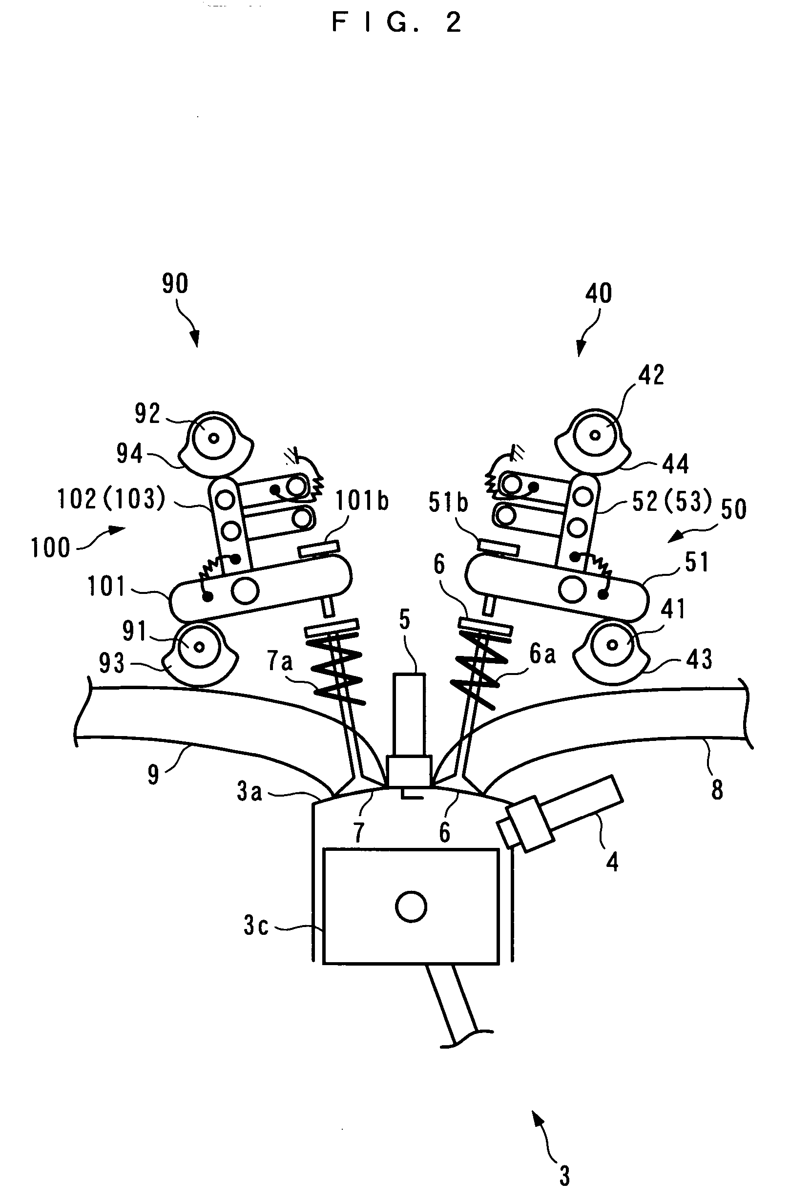
The invention will now be described in detail with reference to the drawings showing a preferred embodiment thereof. Referring first to FIGS. 1 and 2, there is schematically shown the arrangement of an internal combustion engine 3 (hereinafter simply referred to as “the engine 3”) to which is applied a control system 1 according to the present embodiment. FIG. 3 schematically shows the arrangement of the control system 1. As shown in FIG. 3, the control system 1 includes an ECU 2. The ECU 2 carries out control processes, as described hereinafter, including a process for control of valve timing of intake valves 6 and exhaust valves 7, based on operating conditions of the engine 3.

The engine 3 is an inline four-cylinder gasoline engine installed on an automotive vehicle, not shown, and has first to fourth cylinders #1 to #4 (see FIG. 5). Further, the engine 3 includes main fuel injection valves 4 (only one of which is shown) and spark plugs 5 (only one of which is shown), provided ...


PUM


Abstract

A control system for an internal combustion engine, which is capable of reducing exhaust emissions during and after the start of the engine. A control system is capable of changing the valve-closing timing of intake valves relative to the valve-opening timing thereof as desired using a variable intake valve actuation assembly. The control system includes an ECU. The ECU sets a target auxiliary intake cam phase to a start value that sets the valve-closing timing of the intake valves to retarded-closing timing, during starting of the engine, and to a catalyst warmup value that sets the same to timing closer to timing in the Otto cycle operation, during catalyst warmup control after the start of the engine.

Description

BACKGROUND OF THE INVENTION 1. Field of the Invention The present invention relates to a control system for controlling valve timing and the like of intake valves and exhaust valves of an internal combustion engine, during starting of the engine and catalyst warmup control after the start of the engine. 2. Prior Art Conventionally, a control system for controlling valve timing of intake valves of an internal combustion engine has been proposed e.g. in Japanese Laid-Open Patent Publication (Kokai) No. H11-153075 (page 15, FIGS. 4 and 17). This engine includes a variable cam phase mechanism that changes the relative phase between each intake cam and the associated intake camshaft to thereby change the valve-closing timing and valve-opening timing of the intake valves, i.e. the valve timing of the intake valves, while maintaining the same valve open time over which each intake valve is open. This control system advances the valve timing of the intake valves at the start of the engi...

Claims


Application Information

Patent Timeline
IPC IPC(8): F02D43/00F01L1/08F01L1/18F01L1/344F01L13/00F01N3/20F01N3/24F02D13/02F02D31/00F02D41/00F02D41/02F02D41/06F02D41/14F02D45/00
CPCF01L1/08Y02T10/42F01L1/3442F01L13/0047F01L2001/34483F01L2201/00F01L2800/00F01L2820/02F02D13/0211F02D13/023F02D13/0246F02D31/002F02D41/0002F02D41/0255F02D41/062F02D41/1403F02D2041/001F02D2041/1416F02D2200/0402Y02T10/18Y02T10/26F01L1/18Y02T10/12Y02T10/40
Inventor YASUI, YUJIYONEKAWA, AKIYUKI
Owner HONDA MOTOR CO LTD
Why Eureka
Try Eureka