LED compensation circuit

a compensation circuit and led technology, applied in the direction of electric variable regulation, process and machine control, instruments, etc., can solve the problems of reducing the service life of the circuit, increasing the size of the light bar, adversely affecting the aerodynamic characteristics of the vehicle, etc., to achieve convenient customization by the user, improve the effect of performance, and prolong the life cycl

Inactive Publication Date: 2005-01-06
911 EMERGENCY PRODS
View PDF75 Cites 32 Cited by
  • Summary
  • Abstract
  • Description
  • Claims
  • Application Information

AI Technical Summary

Benefits of technology

[0027] A principal advantage of the present invention is the optimization of performance of a warning signal light which is capable of producing several different types of light signals or combinations of light signals.
[0028] Another principal advantage of the present invention is to be rugged and have a relatively longer life cycle than traditional warning signal lights.
[0029] Still another principal advantage of the present invention is to produce a truer or pure light output color without the use of filters.
[0030] Still another principal advantage of the present invention is to allow the user to adjust the color of the light signal without having to make a physical adjustment from a multi-colored panel.
[0031] Still another advantage of the present invention is that the light signal produced may be easily customized by the user via a controller or microprocessor.
[0032] Still another principal advantage of the present invention is the provision of an LED light source which is formed of a relatively simple and inexpensive design, construction, and operation and which fulfills the intended purpose without fear of failure or injury to persons and / or damage to property.

Problems solved by technology

Many problems exist with the known methods for producing warning light signals.
One particular problem with known light sources is their reliance on mechanical components to revolve or oscillate the lamps to produce the desired light signal.
Additionally, these components increase the size of the light bar or emergency lights which may adversely affect the vehicles aerodynamic characteristics.
Moreover, there is an increased likelihood that a breakdown of the light bar or light source will occur requiring the repair or replacement of the defective component.
Finally, the known light bars and light sources require a relatively large amount of electrical current during operation.
The demands upon the electrical power system for a vehicle may therefore exceed available electrical resources reducing optimization of performance.
These lamps emanate large amounts of heat which is difficult to dissipate from a sealed light enclosure or emergency light and which may damage the electronic circuitry contained therein.
In addition, these lamps consume large amounts of current requiring a large power supply or large battery or electrical source which may be especially problematic for use with a vehicle.
These lamps also generate substantial electromagnetic emissions which may interfere with radio communications for a vehicle.
Finally, these lamps, which are not rugged, have relatively short life cycles necessitating frequent replacement.
Another problem with the known warning signal lights is the use of filters to produce a desired color.
Furthermore, filters fade or flake over time rendering the filters unable to consistently produce a desired color for observation in an emergency situation.
These problems associated with traditional signaling lamps are exacerbated by the fact that creating multiple light signals requires multiple signaling lamps.
Further, there is little flexibility in modifying the light signal created by a lamp.
For example, changing a stationary lamp into one that rotates or oscillates would require a substantial modification to the light bar which may not be physically or economically possible.
Another problem with the known warning signal lights is the absence of flexibility for the provision of variable intensity for the light sources to increase the number of available distinct and independent visual light effects.
Also, no warning light signals are known which provide a regular pattern of variable or modulated light intensity for a warning signal light to provide a desired type of lighting effect.
Further, no warning light signals are known which combine a desired type of light effect with either irregular variable light intensity or regular modulated light intensity to provide a unique and desired combination lighting effect.
It has also not been known to provide alternative colored LED light sources which may be electrically controlled for the provision of any desired pattern of light signal such as flashing, pulsating, oscillating, modulating, variable, rotational, alternating, strobe, and / or combination light effects.
Another problem encountered during use of LED light sources is the optimization of the efficiency of the LED light sources for the provision of maximized illumination.
Insufficient electrical current provided to the LED's results in non-optimized illumination, and excess current may burn the LED's out, damage the driving circuitry, and / or reduce the operational life of the LED's.
The maximization of the illumination for individual or groups of LED's is therefore problematic due to the inclusion of the LED's within standardized electrical circuitry.
Customization of each circuit containing individual LED's is cost prohibitive.
Further, individual LED's may degrade at different rates.

Method used


Image

  • LED compensation circuit
  • LED compensation circuit
  • LED compensation circuit

Examples


Embodiment Construction

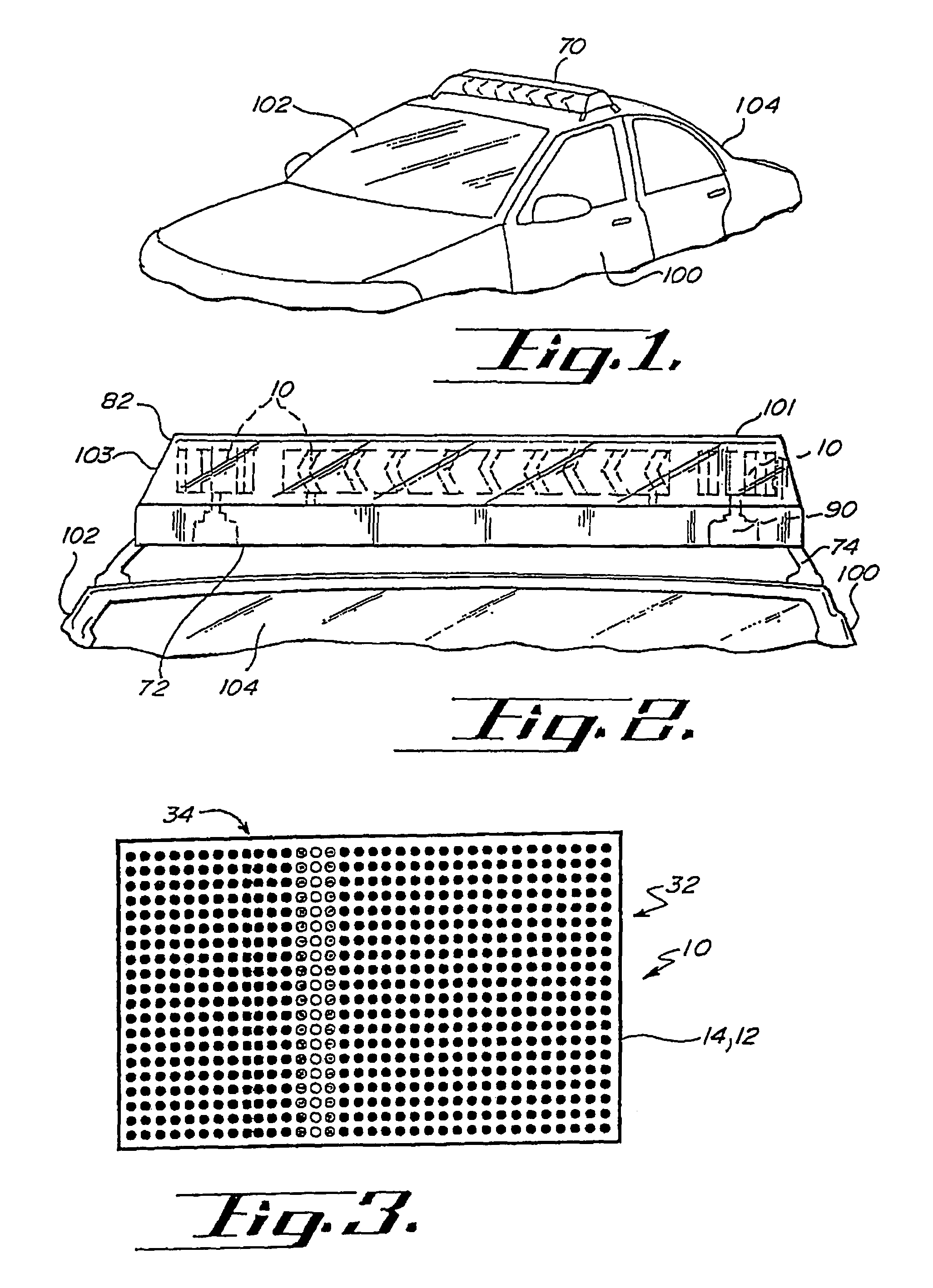
[0083] A warning signal light according to the principles of the invention is indicated generally herein as numeral 10. FIGS. 1 and 2 depict light bar 70 mounted to an emergency vehicle 104. Light bar 70 includes base 72, mounting means 74, cover 82, and warning signal lights 10. Also included in light bar 70 may be gyrators 90 used to impart motion to warning signal lights 10.

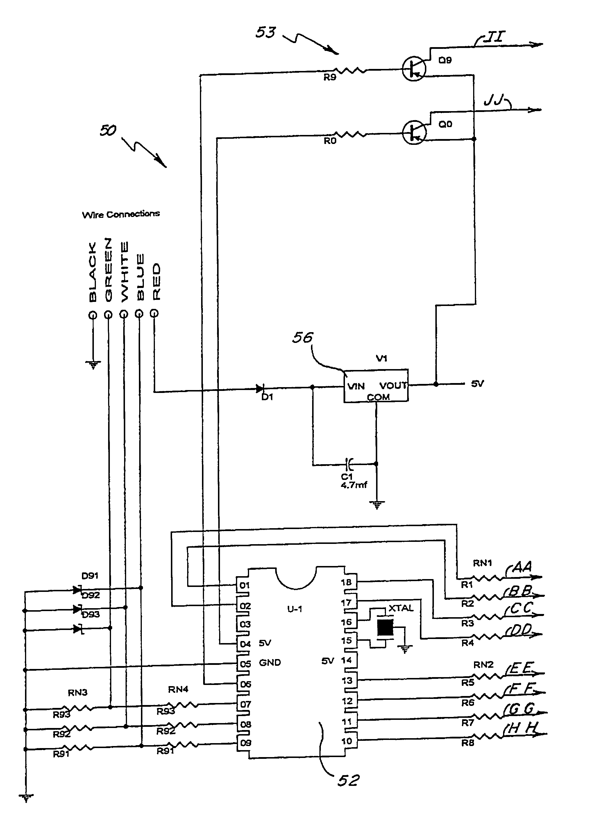
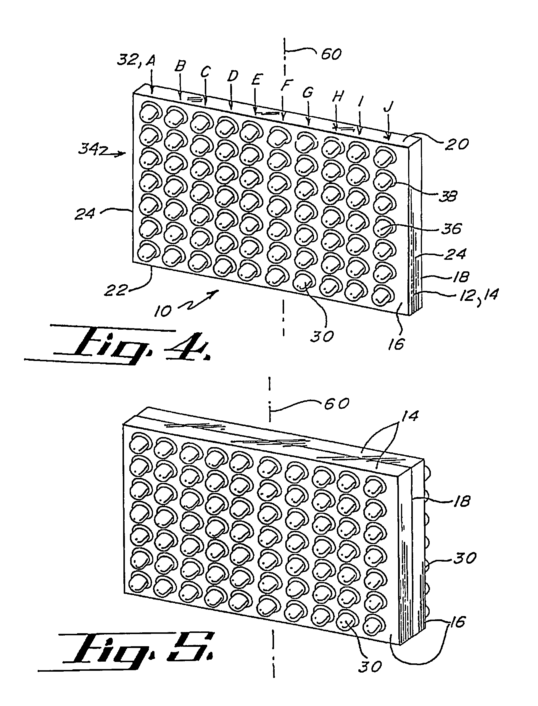
[0084] Referring to FIG. 4, warning signal light 10 comprises light support 12, light sources 30, controller 50 (shown in FIG. 6), and connecting portion 40 for attaching the warning signal light 10 to light bar 70 or gyrator 90. The warning signal light 10 operates to create a warning signal for use by an emergency vehicle 104 by selectively activating light sources 30 using controller 50. Alternatively, warning signal light 10 may be formed of a solitary LED light source 30.

[0085] Light sources 30 are preferably light emitting diodes (LED's) and are generally arranged in modules formed of groups of LED's a...


PUM


Abstract

A compensating circuit initially adjusts the electrical parameters for a plurality of light emitting diodes for inclusion within standardized specifications for the electrical system of a light fixture. The compensating circuit includes a compensator which may be a zener diode positioned downstream from a series of light emitting diodes. The compensating software monitors the current drop across a series of light emitting diodes and initially assigns a current analysis value based upon the frequency and / or type of light emitting diode utilized. The compensating software then compares a signal representative of the current drop to the current analysis value to increase and / or decrease current exposed to the light emitting diodes to maximize illumination from the light sources.

Description

RELATED CASES [0001] This application corresponds and claims priority to U.S. Provisional Patent Application No. 60 / 209,766 entitled Duty Cycle Compensation Circuit DC3 filed Jun. 6, 2000 which is incorporated herein by reference in its entirety.BACKGROUND OF THE INVENTION [0002] Light bars or emergency lights of the type used on emergency vehicles such as fire trucks, police cars, and ambulances, utilize warning signal lights to produce a variety of light signals. These light signals involve the use of various colors and patterns. In the past these warning signal lights have utilized incandescent and halogen light sources having reflective back support members and colored filters. [0003] Many problems exist with the known methods for producing warning light signals. One particular problem with known light sources is their reliance on mechanical components to revolve or oscillate the lamps to produce the desired light signal. Additionally, these components increase the size of the l...

Claims


Application Information

Patent Timeline
Patent Type & Authority Applications(United States)
IPC IPC(8): H05B44/00
CPCH05B33/0848H05B45/14
Inventor PEDERSON, JOHN C.
Owner 911 EMERGENCY PRODS
Why Eureka
Try Eureka