Wireless network system and communication method employing both contention mode and contention-free mode

Inactive Publication Date: 2005-01-06
REDWOOD TECHNOLOGIES LLC
View PDF6 Cites 44 Cited by
  • Summary
  • Abstract
  • Description
  • Claims
  • Application Information

AI Technical Summary

Benefits of technology

If it is found from the re-test that relevant control parameters, such as the transmission level and the antenna directivity, are substantially identical to those measured in the original test, the conclusion is that the communication station has not moved but the communications have been interrupted by other causes. To deal with that, a packet requesting a change of time-slots is transmitted fr

Problems solved by technology

This may not ensure avoidance of collision of transmission signals but it minimizes the possibility of collision.
Hence, during the transmission of packets, discrepancies (jitters) may occur, and it will thus be impossible to predict the precise time of arrival of packets at the receiver station.
If the timing is altered, jitters may accordingly occur even in this method.
Moreover, the synchronous transm

Method used


Image

  • Wireless network system and communication method employing both contention mode and contention-free mode
  • Wireless network system and communication method employing both contention mode and contention-free mode
  • Wireless network system and communication method employing both contention mode and contention-free mode

Examples


Embodiment Construction

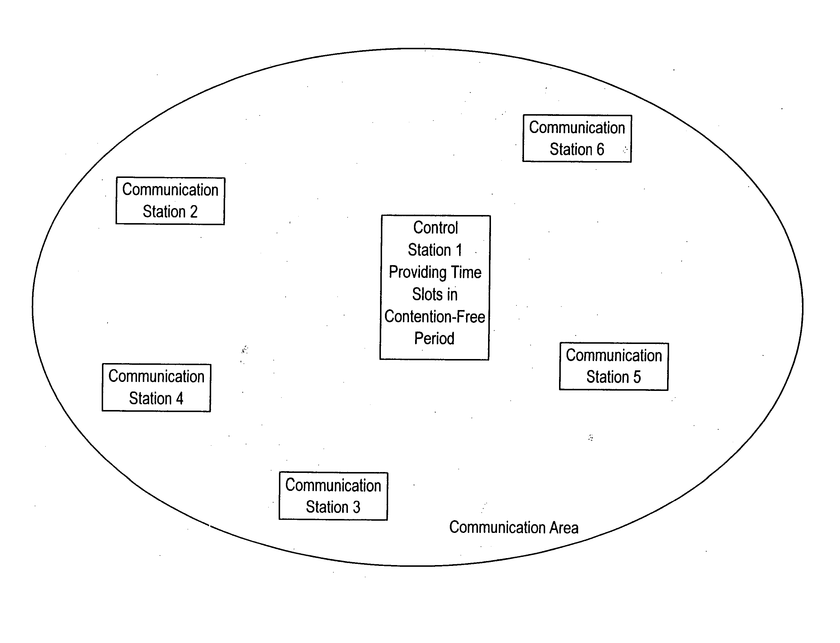
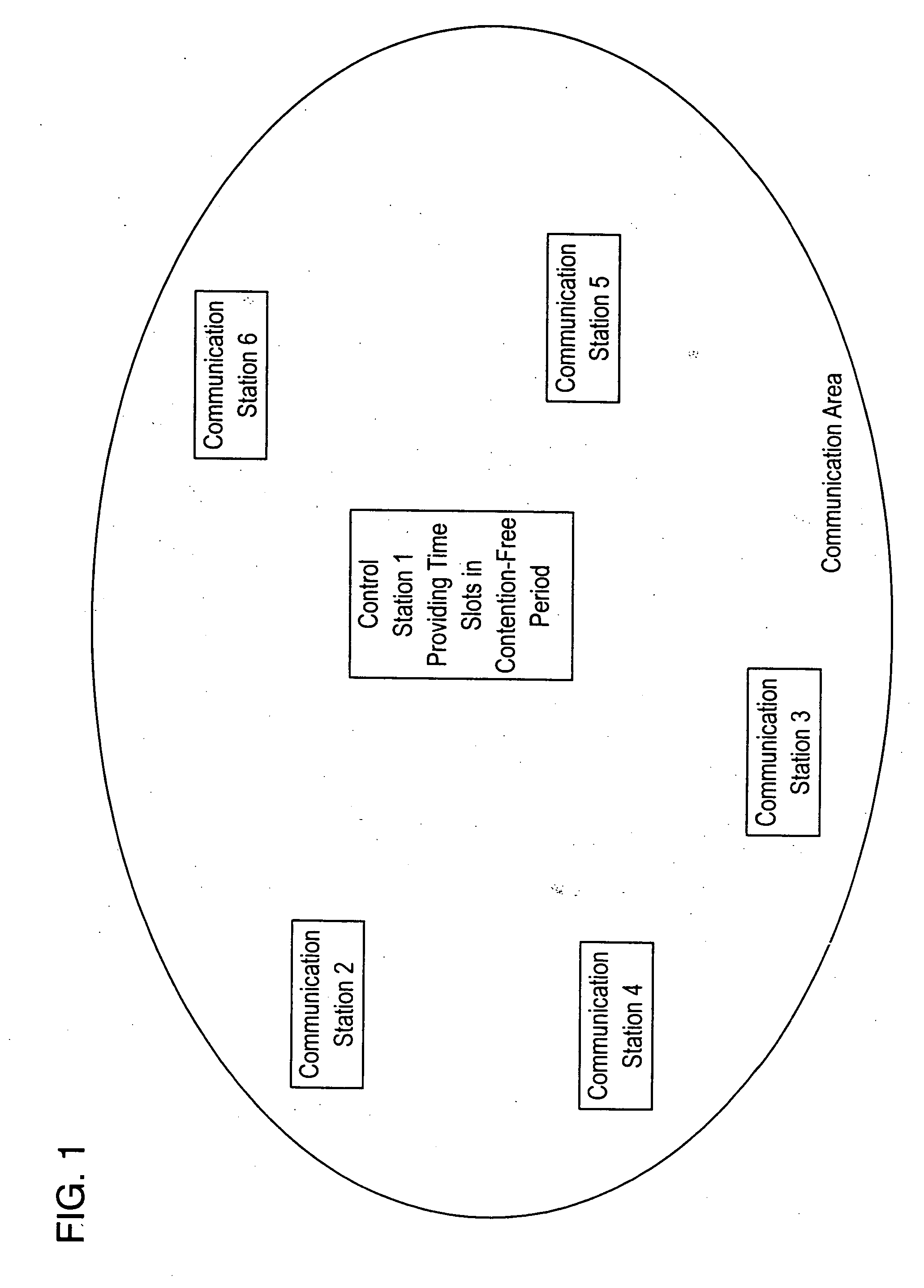
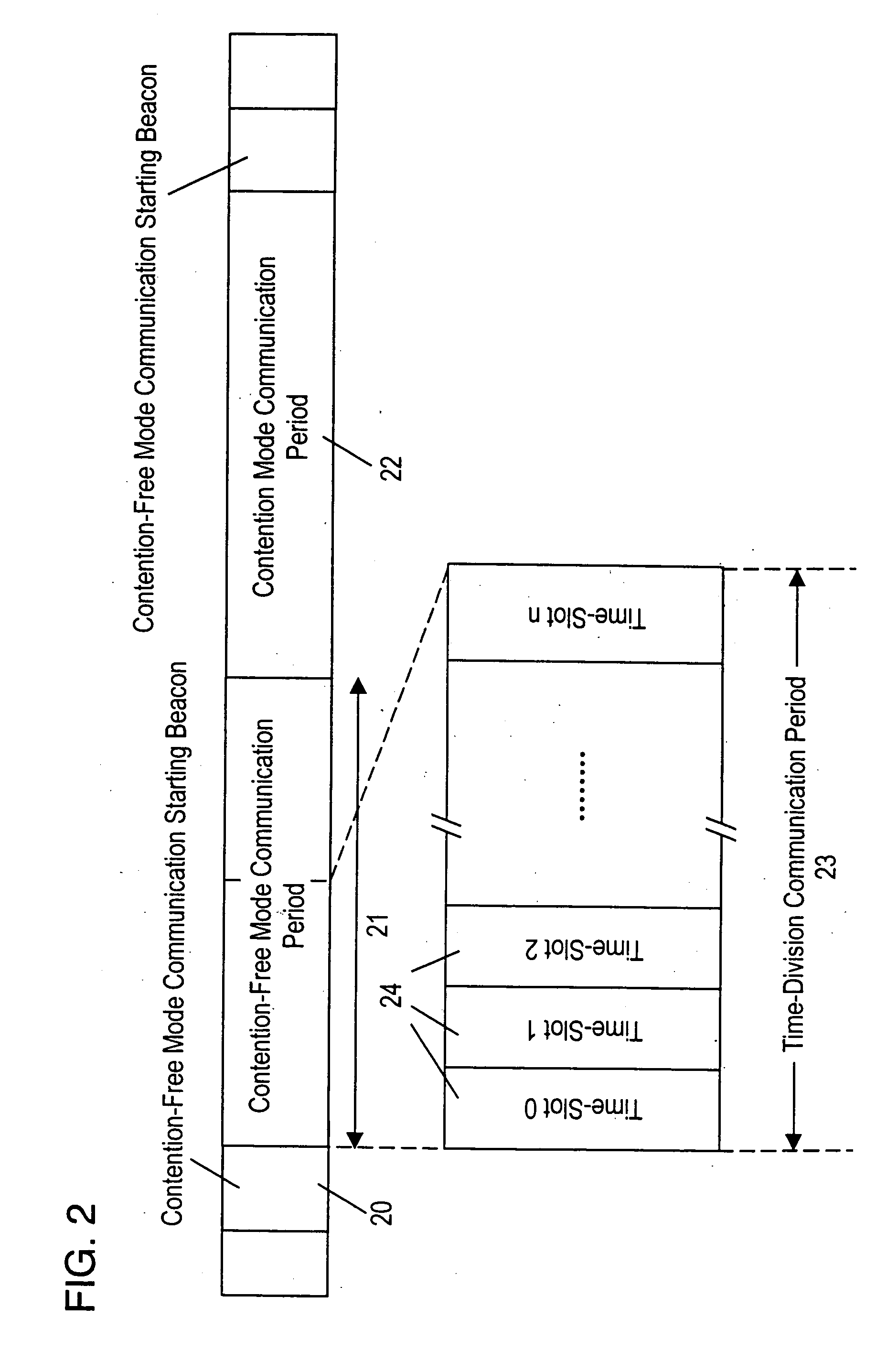
FIG. 1 illustrates an arrangement of a wireless network system employing the present invention as discussed hereinbelow. FIG. 7 is a time sequence for the wireless network system used with the present invention. The time sequence is identical to that specified in IEEE 802.11, although variations of this sequence may be employed. As a series of beacons is transmitted at constant intervals of time from the control station, contention-free mode transmission, which continues during a contention-free period (CFP), is initiated. The Interval of the contention-free period (CFP) is determined by a set of contention-free (CF) parameters included in the beacons as a CFP period. The transmission is maintained in the contention-free mode throughout the maximum length of the contention-free period (CFP Max Duration), allowing the contention-free mode communications to be carried out by the communication stations as triggered by a polling operation of the control station. The contention-free peri...


PUM


Abstract

A network communication system is provided whereby communication stations can obtain priority for data transmission to communicate directly with each other in a contention-free mode communication period independently of a polling operation of the control station. The control station emits a series of beacons at equal intervals to initiate contention-free mode communication at the completion of a predetermined number of beacons. During the maximum contention-free mode communication period a contention-free communication operation is initiated, for allowing contention-free mode transmission, by a polling operation by the control station. A series of time-slots is imaginarily provided at equal intervals from the start of the contention-free period throughout the maximum contention-free period. A communication station conducts a call-connection procedure in order to obtain a priority for data transmission in a given set of time-slots.

Description

FIELD OF THE INVENTION The present invention relates to a communication method and wireless network system for exchanging data in the form of digital signals. DESCRIPTION OF THE RELATED ART One known data communication system with wireless transmission technology is the accessing method specified in IEEE 802.11. Such a wireless network system is schematically explained referring to FIG. 15. In the FIG. 15 system, upon finding that a particular transmission channel is active, control station 1 (an accessing point) transmits a control signal of a constant period, called a beacon. Control station 1 controls a group of communication stations 2, 3, 4, 5, and 6 for exchanging packets of data. The communication stations 2-6 are notified by the beacon that the channel is active. Each communication station then registers itself as a subscriber for data exchange under control station 1. Then, the communication station is qualified to participate in packet data communication on the transmis...

Claims


Application Information

Patent Timeline
IPC IPC(8): H04B7/24H04L12/28H04W4/04H04W28/00H04W74/02H04W74/04H04W74/08H04W84/12
CPCH04W74/02
Inventor WATANABE, YOSHINORIKOBAYASHI, HIROKAZUDOI, HIROSHI
Owner REDWOOD TECHNOLOGIES LLC
Why Eureka
Try Eureka