Laser marking system

a laser marking and indicia technology, applied in the field of indicia, can solve the problems of insufficient repositioning to form complete characters or graphics, limited accuracy of known embodiments of this system, etc., and achieve the effect of facilitating separation of function, reducing the amount of vibration isolation apparatus, and improving vibration immunity

Inactive Publication Date:
View PDF9 Cites 15 Cited by
  • Summary
  • Abstract
  • Description
  • Claims
  • Application Information

AI Technical Summary

Benefits of technology

According to another aspect of the invention, the laser energy microinscribing system includes a semiconductor excited Q-switched solid state laser energy source, a cut gemstone mounting system, having an aperture, an optical system for focusing laser energy from the laser energy source, through said aperture onto a cut gemstone, a displaceable stage for moving said gemstone mounting system with respect to said optical system so that said focused laser energy is presented to desired positions on said gemstone, having a control input, an imaging system for viewing the gemstone from a plurality of vantage points, and a rigid frame supporting said laser, said optical system and said stage in fixed relation, to resist differential movements of said laser, said optical system and said stage and increase immunity to vibrational misalignments. By employing a laser system with low cooling and power requirements, the device may be made self contained and compact. By minimizing the size of the apparatus, and enclosing the device in a rigid frame or chassis, vibration immunity is improved. Thus, as compared to systems employing flashlamp excited lasers, substantial vibration isolation apparatus is eliminated.
According to another aspect of the invention, prior to any markin

Problems solved by technology

The accuracy of known embodiments of this system are limited by vibration and laser steering

Method used


Image

  • Laser marking system
  • Laser marking system
  • Laser marking system

Examples


Embodiment Construction

The detailed preferred embodiments of the invention will now be described with respect to the drawings. Like features of the drawings are indicated with the same reference numerals.

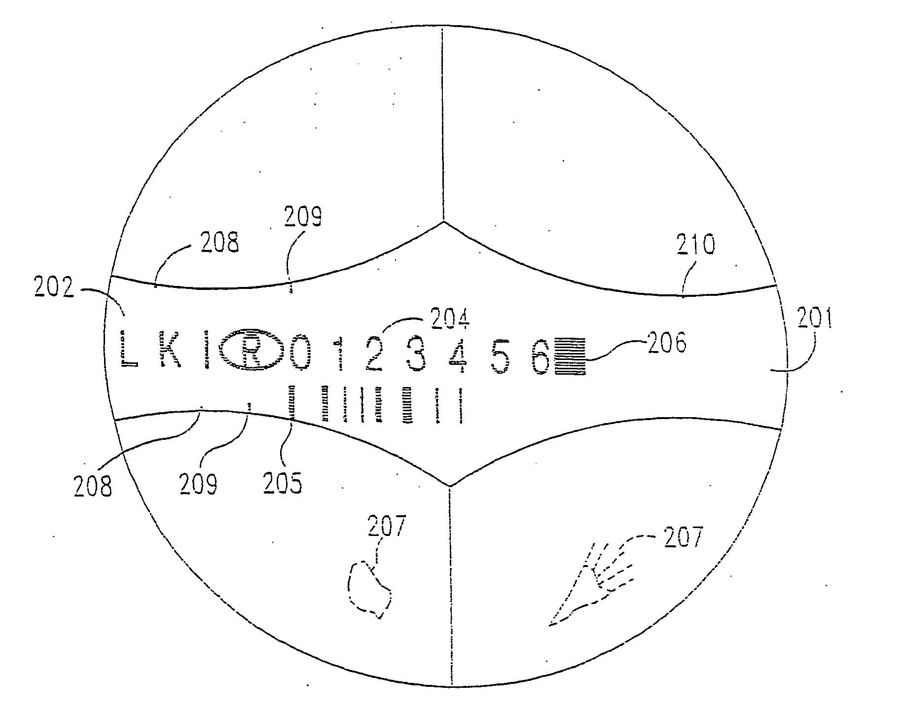
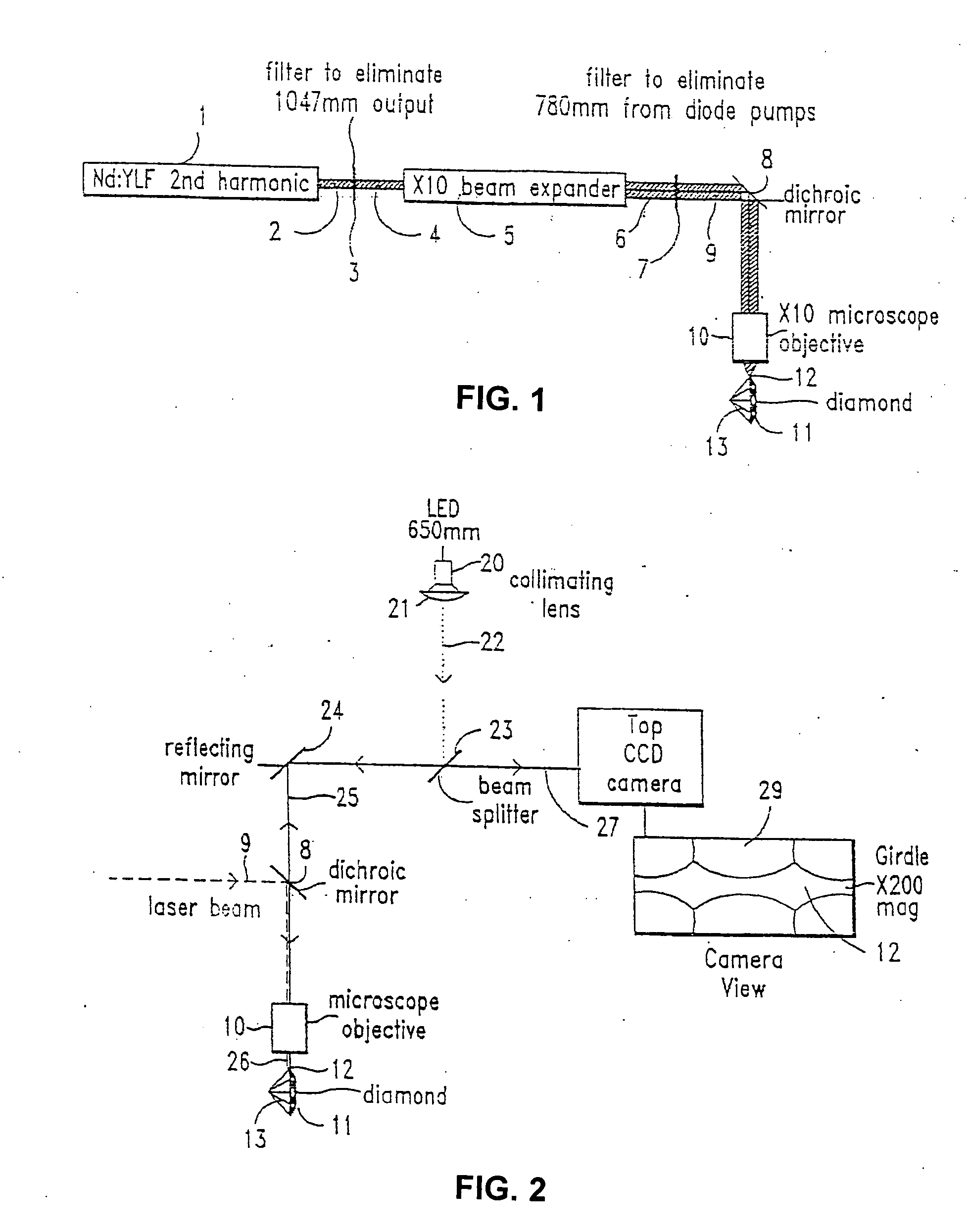
The system ac cording to the present invention may be used to micro-inscribe alpha / numeric characters on the girdle of diamonds 13. It is based on a pulse laser 1, and preferably a Q-switched laser diode pumped solid state laser, to provide minimum volume and installation requirements, and optimum compatibility with any office environment.

A preferred laser based inscribing system according to the present invention thus contains the following primary elements:

In a vibration isolated frame 140 with shock absorbers 141, at the positions of support:

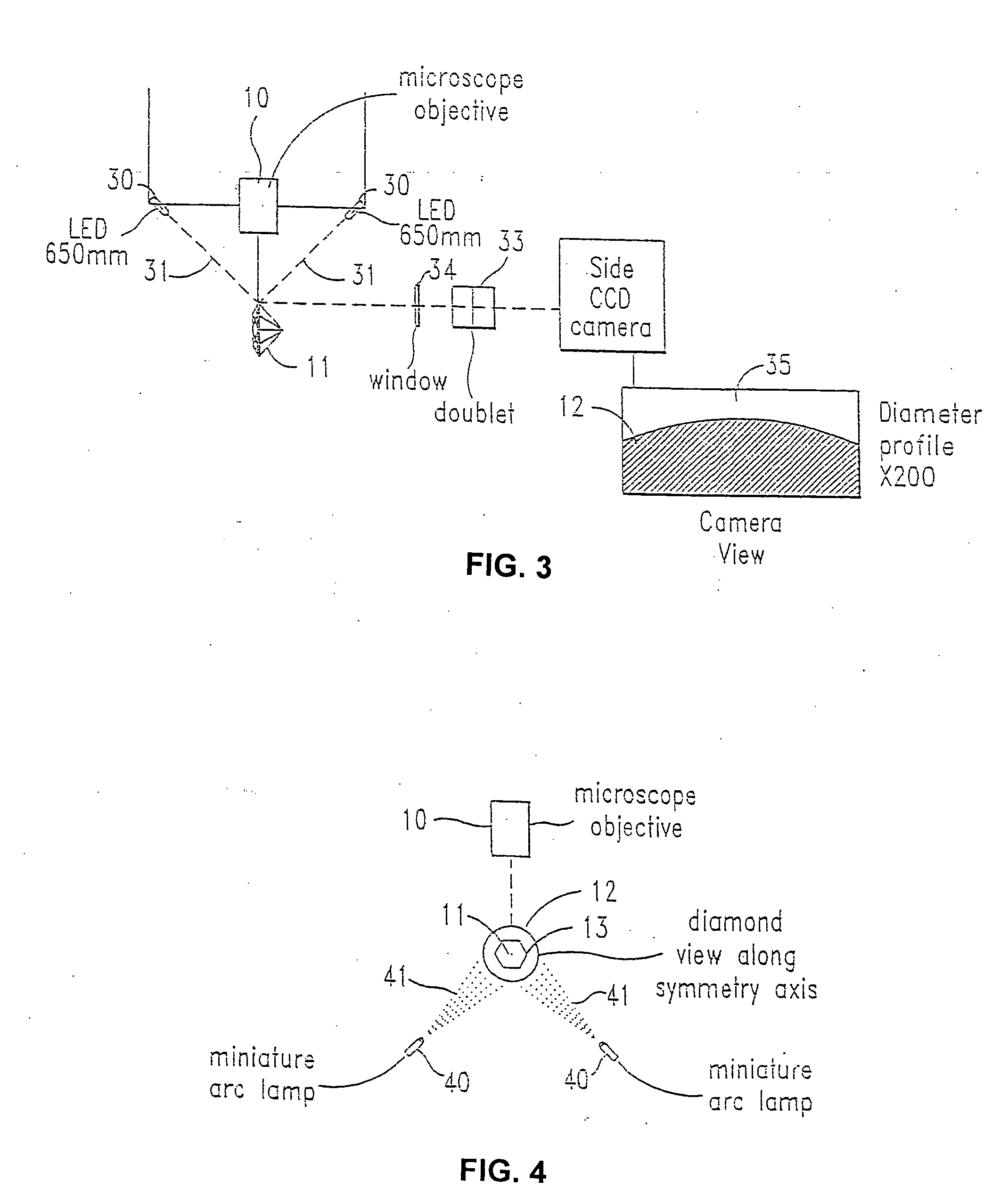
(1) Laser diode pumped laser 1 and programmable power supply 14, with a Beam Expander 5. (2) Optical assembly containing guiding 8 and focusing optics 10, miniature CCD cameras 25, 32 and illumination system. (3) XYZ motion stages 50 (with Z elevator sta...


PUM

PropertyMeasurementUnit
Lengthaaaaaaaaaa
Lengthaaaaaaaaaa
Lengthaaaaaaaaaa

Abstract

A laser energy microinscribing system, comprising a semiconductor excited Q-switched solid state laser energy source; a cut gemstone mounting system, allowing optical access to a mounted workpiece; an optical system for focusing laser energy from the laser energy source onto a cut gemstone; a displaceable stage for moving said gemstone mounting system with respect to said optical system so that said focused laser energy is presented to desired positions on said gemstone, having a control input; an imaging system for viewing the gemstone from a plurality of vantage points; and a rigid frame supporting said laser, said optical system and said stage in fixed relation, to resist differential movements of said laser, said optical system and said stage and increase immunity to vibrational misalignments. The laser energy source is preferably a semiconductor diode excited Q-switched Nd:YLF laser with a harmonic converter having an output of about 530 nm. The system may further comprise an input for receiving marking instructions; a processor for controlling said displaceable stage based on said marking instructions and said imaging system, to selectively generate a marking based on said instructions and a predetermined program; and a storage system for electronically storing information relating to images of a plurality of workpieces. A secure certificate of authenticity of a marked workpiece is also provided.

Description

FIELD OF THE INVENTION The present invention relates to the field of inscribing indicia on a surface of gemstones, and more particularly to a system employing a Q-switched pulse laser for forming markings on a portion of a gemstone. BACKGROUND OF THE INVENTION A known system, as described in U.S. Pat. No. 4,392,476, incorporated herein by reference, for inscribing diamonds includes a Nd:YAG (1.06 μm, frequency doubled) Q-switched laser which marks diamonds by graphitizing the surface at a laser focal point. The beam position is computer controlled to create overlapping treated regions. The accuracy of known embodiments of this system are limited by vibration and laser steering system accuracy. U.S. Pat. No. 4,467,172, incorporated herein by reference, describes a laser beam diamond inscribing system, which provides a Q-switched flashlamp pumped YAG laser (1.06 μm, frequency doubled) with the diamond mounted on a computer-controlled positioning table for inscribing alphanumeric ch...

Claims


Application Information

Patent Timeline
IPC IPC(8): B23K26/00A44C27/00B23K26/02B23K26/03B23K26/04B23K26/06B23K26/08B23K26/10B23K26/18B25H7/04B44C1/22B44F1/12G01N21/87G06K1/12H01R13/658
CPCB23K26/032B23K26/041B23K26/06B23K26/0639B23K26/0643B23K26/0648B23K26/0665B23K26/0861B23K26/365B23K26/403B41M5/262B44B3/009B44B7/007B44C1/228G06K1/126H01R13/65807B23K26/043B23K26/04B23K26/064B23K26/042G01N21/87B23K26/361B23K2103/30B23K2103/50
Inventor KAPLAN, GEORGE R.SHACHRAI, AVIGDORANNER, ODEDGURVICH, LEONID
Why Eureka
Try Eureka