Cleaning apparatus for cleaning objects to be treated with use of cleaning composition

Inactive Publication Date: 2005-01-13
KOBE STEEL LTD +1
View PDF7 Cites 34 Cited by
  • Summary
  • Abstract
  • Description
  • Claims
  • Application Information

AI Technical Summary

Benefits of technology

[0009] In view of the above, it is an object of the present invention to provide a cleaning apparatus that enables to minimize contamination due to leakage of harmful materials therefrom to thereby suppress adverse effect on human beings due to the contamination, wherein th

Problems solved by technology

Despite the merit that the high-pressure carbon dioxide functions as a low-viscosity solvent, it does not exhibit sufficient solubility of dissolving unnecessary materials, and does not provide satisfactory cleaning performance, if used alone.
As a further study has been carried out, however, there has been found a drawback that cleaning semiconductor wafers formed with an interlayer insulation film made of a low-k dielectric material (so-called “low-k film”), which have been heavily used recently, by a supercritical fluid containing a basic substance may degrade the quality of the semicondu

Method used


Image

  • Cleaning apparatus for cleaning objects to be treated with use of cleaning composition
  • Cleaning apparatus for cleaning objects to be treated with use of cleaning composition
  • Cleaning apparatus for cleaning objects to be treated with use of cleaning composition

Examples


first embodiment

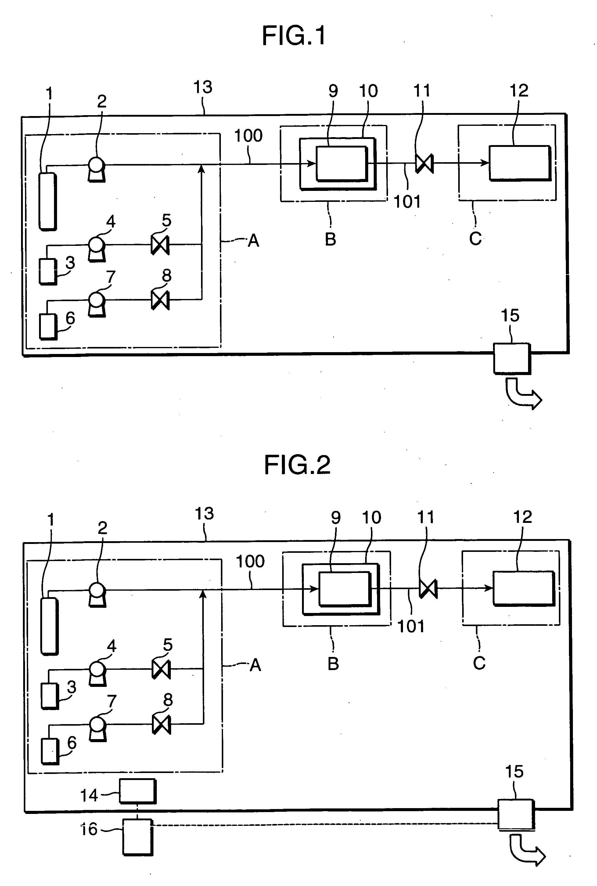
[0041]FIG. 1 is an illustration showing a cleaning apparatus in accordance with a first embodiment of the present invention. In FIG. 1, the symbol A denotes high pressure fluid supplying means (high pressure fluid supplying section), B denotes a washing section, and C (specifically, the reference numeral 12) denotes a storing section, respectively. The reference numeral 11 denotes a pressure regulating valve, 15 denotes first exhaust means, 100 and 101 denote pathways, respectively.

[0042] The cleaning apparatus shown in FIG. 1 is provided with a carbon dioxide storing tank (storing vessel) 1, a carbon dioxide feeding pump 2, a cleaning component storing tank 3, a cleaning component feeding pump 4, a switching valve 5, a rinsing component storing tank 6, a rinsing component feeding pump 7, and a switching valve 8, which constitute the high pressure fluid supplying section A. The cleaning apparatus is further provided with a high pressure washing vessel 9, and a thermostatic chamber ...

second embodiment

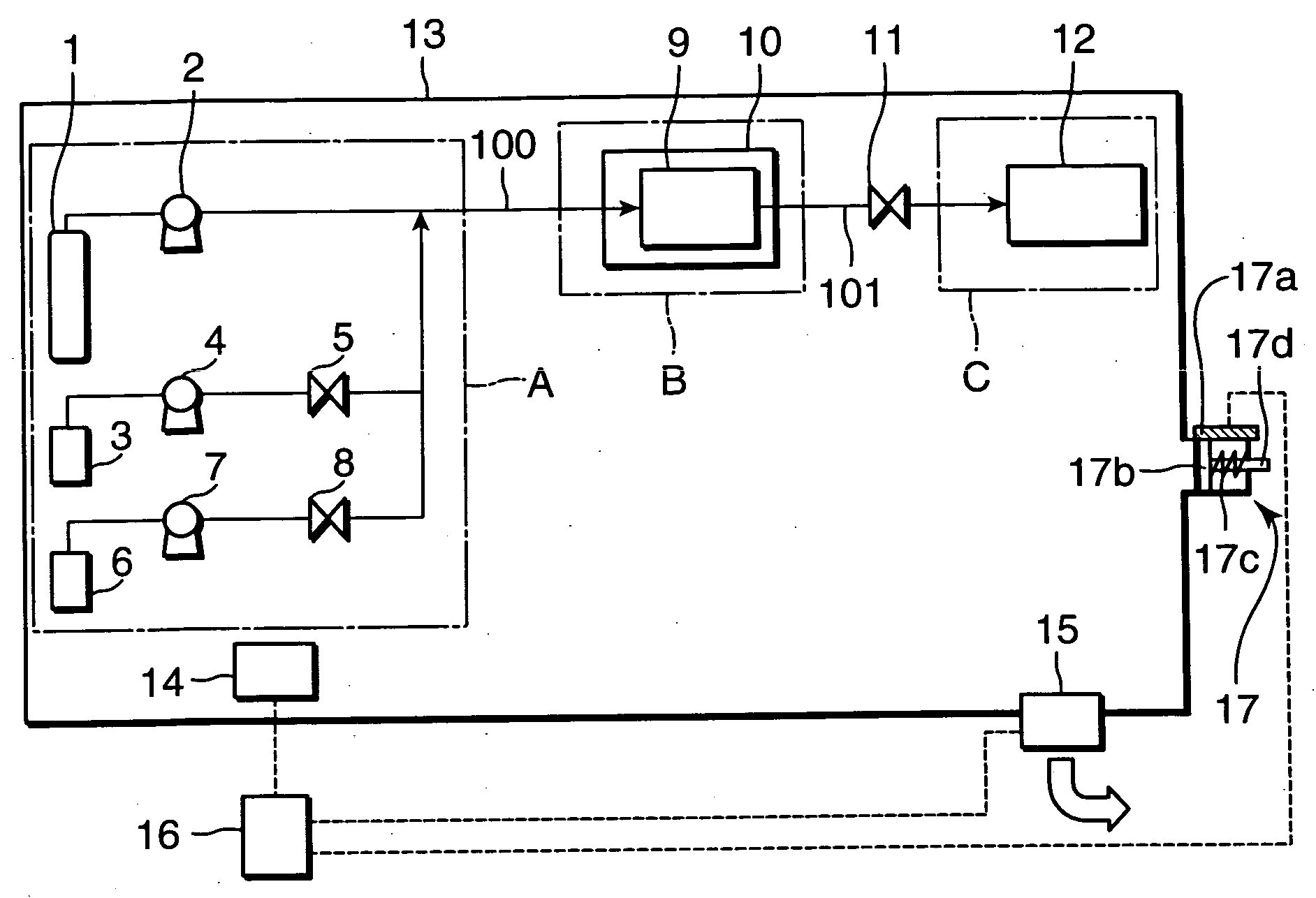
[0055]FIG. 2 is an illustration showing a cleaning apparatus in accordance with a second embodiment of the present invention. The cleaning apparatus shown in FIG. 2 is provided with first fluid leak detecting means 14 and first exhaust amount controlling means 16, in addition to elements equivalent to the elements in the first embodiment as shown in FIG. 1. It should be noted that the elements in the second through seventh embodiments which are equivalent to those in the first embodiment are denoted at the same reference numerals. The first fluid leak detecting means 14 and the first exhaust amount controlling means 16, and the first exhaust amount controlling means 16 and first exhaust means 15 are electrically connected with each other via wirings, respectively. The wirings are denoted by the dotted lines in FIG. 2. In FIG. 2, a first gas amount detector 14 serves as the first fluid leak detecting means 14.

[0056] As shown in FIG. 2, arranging the first gas amount detector 14 in a...

third embodiment

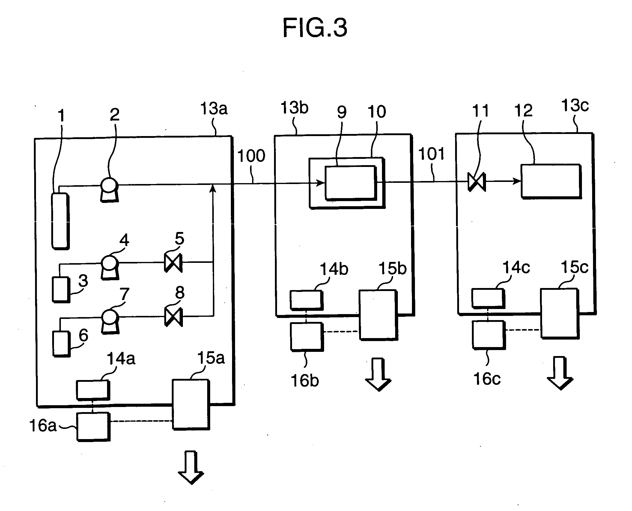
[0062]FIG. 3 is an illustration showing a cleaning apparatus in accordance with the third embodiment of the present invention. In FIG. 3, a carbon dioxide storing tank 1, a carbon dioxide feeding pump 2, a cleaning component storing tank 3, a cleaning component feeding pump 4, a switching valve 5, a rinsing component storing tank 6, a rinsing component feeding pump 7, and a switching valve 8 are housed in a sealed unit 13a. A high pressure washing vessel 9, and a thermostatic chamber 10 are housed in a sealed unit 13b. A pressure regulating valve 11 and a storing tank 12 are housed in a sealed unit 13c. The sealed unit 13a is provided with a fluid leak detector 14a, exhaust means 15a, and exhaust amount controlling means 16a. Likewise, the sealed unit 13b is provided with a fluid leak detector 14b, exhaust means 15b, and exhaust amount controlling means 16b. Likewise, the sealed unit 13c is provided with a fluid leak detector 14c, exhaust means 15c, and exhaust amount controlling me...


PUM


Abstract

Provided is a cleaning apparatus for cleaning an object to be treated by contacting the object to be treated with a high pressure fluid of a cleaning composition containing a cleaning component as an essential ingredient. The cleaning apparatus includes high pressure fluid supplying means for supplying the high pressure fluid of the cleaning composition, a high pressure washing vessel for removing unnecessary materials deposited on the object to be treated by contacting the object to be treated with the high pressure fluid of the cleaning composition therein, a storing vessel for storing a waste high pressure fluid of the cleaning composition carrying the unnecessary materials therein, and a sealed structure for sealably housing the high pressure fluid supplying means, the high pressure washing vessel, and the storing vessel therein. The sealed structure has first exhaust means for exhausting the gas remaining in the sealed structure therefrom.

Description

BACKGROUND OF THE INVENTION [0001] 1. Field of the Invention [0002] The present invention relates to an apparatus for cleaning microstructures having asperities (protrusions and recesses) such as semiconductor wafers, as objects to be treated. [0003] 2. Description of the Related Art [0004] It is indispensable to remove unnecessary materials deposited on semiconductor wafers in a process of manufacturing semiconductor wafers. For instance, there is often used a step of forming patterns on semiconductor wafers with use of photoresist. The photoresist used in a masking step becomes unnecessary after an etching step, and is removed by carrying out oxygen plasma ashing or a like technique (an ashing step). After the ashing step, it is required to carry out a washing step of stripping and removing, from the wafer surfaces, unnecessary materials such as etching residues, and photoresist residues that have not been removed by the ashing step. The washing step is a crucial step in the semic...

Claims


Application Information

Patent Timeline
IPC IPC(8): B08B7/00B08B3/08H01L21/00H01L21/027H01L21/304
CPCH01L21/67051B08B7/0021
Inventor YAMAGATA, MASAHIROOSHIBA, HISANORIINOUE, YOICHIMURAOKA, YUSUKEIWATA, TOMOMISAITO, KIMITSUGU
Owner KOBE STEEL LTD
Why Eureka
Try Eureka