System for manufacturing an inlay panel using a laser

Inactive Publication Date: 2005-01-13
TMC FURNITURE
View PDF4 Cites 26 Cited by
  • Summary
  • Abstract
  • Description
  • Claims
  • Application Information

AI Technical Summary

Benefits of technology

[0040] The computerized laser-cutting and manufacturing process of the present invention has an economical and time-saving aspect whereby an electronically scanned art master can be combined with the precise accuracy and mass production capability of a laser-cutting system to create a unique panel product. Additi

Problems solved by technology

However, while inlays themselves vary widely, there are significant difficulties in the art and industry of creating inlay panels.
One such difficulty is that the industry is labor intensive and requires a high degree of skill from the artisan.
Consequently, the resulting product is correspondingly expensive.
In addition, cutting both the positive and negative images required by an inlay is tedious.
This known system, however, falls short of efficiently controlling the design accuracy and work efficiency.
However, router based systems are limited in the quality of the detail that can be cut.
Moreover, the design tolerances, which are of particular importance in the corners of the design, are limited by the diameter of the router's cutting head.
Generally, the cutting head must be of sufficiently diameter to withstand the cutting of many boards, and therefore delicate and detailed patterns are not achievable.
Thus, the inlay designs are limited to only single-plane surfaces.
Generally, the inlay can only be flush, as inlays in raised relief or recessed relief are not achievable.
However, this met

Method used


Image

  • System for manufacturing an inlay panel using a laser
  • System for manufacturing an inlay panel using a laser
  • System for manufacturing an inlay panel using a laser

Examples


Embodiment Construction

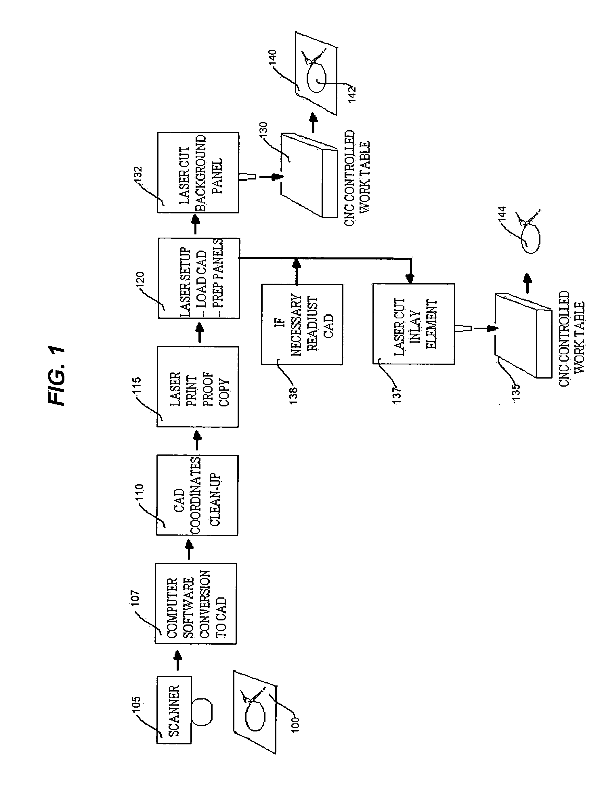
[0060]FIG. 1 is a simplified function block and schematic representation that illustrates a laser cutting process for an inlay in accordance with the principles of the invention. As shown in this figure, there is first provided an art master 100 that is provided by a designer (not shown). It is assumed that at this stage of commencement of manufacture the designer has already specified the greater context for the ultimate design of the panel within the furniture or decorative object (whether it be signage, shelf panel, door, etc.). As will be seen in connection with FIG. 2, the article to be manufactured by this illustrative process, is a shelf unit. In addition, this disclosure of a specific illustrative embodiment of the invention will focus on the cutting of a wood veneer, illustratively on a medium density fiberboard (“MDF”) core as the frame panel, and high pressure plastic laminate (“HPPL”) as the inlay element panel.

[0061] Art master 100 may be a hand or mechanically drawn r...


PUM


Abstract

A method of manufacturing an inlayed panel uses the steps of providing an art master rendering as constitute a decorative design for the inlaid panel; scanning electronically the art master to form an art master data file; transferring the art master data file to a CAD software system to form an art master CAD file; coordinating a laser beam to cut-through a first background panel and create negative image voids; driving a CNC laser cutting machine in response to the machine code coordinates; coordinating a laser beam to cut through a second panel for forming positive images that become inlay elements; bonding the first background panel and the second panel; placing the inlay element in appropriate voided spaces; and finishing the composite panel and the inlay elements. A decorative panel is also formed of panel portions cut by laser using data inputted directly into a computer graphics system.

Description

RELATIONSHIP TO OTHER APPLICATION(S) [0001] This application is a continuation-in-part patent application of U.S. Ser. No. 10 / 171,166 filed Jun. 13, 2002, which claims the benefit of U.S. Provisional Application No. 60 / 297,850 filed Jun. 13, 2001.BACKGROUND OF THE INVENTION [0002] 1. Field of the Invention [0003] This invention relates generally to systems for manufacturing panels, and more particularly, to a system for fabricating decorative panels having intricate decorative designs inlaid therein using a laser. [0004] 2. Description of the Related Art [0005] Inlays have been incorporated into the construction of furniture and the decorative arts for centuries. Typical inlay applications vary widely and encompass many different materials and methods from stone plaque with an embedded metal design, to table tops constructed with die-cut veneer of differing wood species assembled jig-saw puzzle style and bonded to a substrate. However, while inlays themselves vary widely, there are ...

Claims


Application Information

Patent Timeline
IPC IPC(8): B44C1/22B44C1/26B44C3/10B44C5/04
CPCB44C1/228B44C1/26Y10T156/1052B44C5/04Y10T156/1077B44C3/10
Inventor RATCLIFFE, BLAKE EDWARD
Owner TMC FURNITURE
Why Eureka
Try Eureka