Acoustic well recovery method and device

a well recovery and acoustic technology, applied in the oil industry, can solve the problems of reducing the permeability or a flow restriction in the region, the pathway through the perforation extended within the formation may clog with residues, and the well may also produce very heavy molecules, so as to reduce the production rate of fluids and reduce the space in the pore. , the effect of reducing the flow ra

Active Publication Date: 2005-01-13
SONOPLUS
View PDF23 Cites 25 Cited by
  • Summary
  • Abstract
  • Description
  • Claims
  • Application Information

AI Technical Summary

Benefits of technology

[0005] After a period of time, the pathways through the perforations extended within the formation may clog with “fines” or residues. This defines the size of the pore that connects with the fluid within the formation, allowing it to flow from the formation, through the cracks or fissures or connected pores, till it reaches the interstitial spaces within the compartment for collection. During this flow, very small solid particles from the formation known as “fines” may flow but instead tend to settle. Whereas the “fines” may be held in a dispersed state for some time, they can group and thus obstruct the space in the pore reducing the production rate of fluids. This can get to be a problem, which in turn feeds upon itself definitely with the decrease in the flow of production. More and more “fines” may deposit themselves within the perforations and obstruct them, tending to prevent even a minimum flow rate.

Problems solved by technology

The problems associated to the aforementioned causes are: plugging of the pores by fine mineral particles that flow together with the fluid to be extracted, precipitation of inorganic crusts, paraffin and asphaltene decantation, clay hydration, invasion of mud solids and mud filtration, invasion of completion fluids and solids resulting from brine injection.
Each one of the reasons just mentioned may cause a decrease in the permeability or a restriction of flow in the region surrounding the well bore.
On the other hand, the well may also produce very heavy molecules.
After a period of time, the pathways through the perforations extended within the formation may clog with “fines” or residues.
Whereas the “fines” may be held in a dispersed state for some time, they can group and thus obstruct the space in the pore reducing the production rate of fluids.
This can get to be a problem, which in turn feeds upon itself definitely with the decrease in the flow of production.
While acidizing is a common treatment for stimulating oil and gas wells it clearly has some drawbacks, namely the high cost of chemicals and waste disposal costs involved.
The acids are often incompatible with the crude oil and may produce thick oily residues within the well.
Precipitates formed after the acid is spent may often be more harmful than the dissolved minerals.
This process is extremely expensive (by a factor about 5 to 10 times more than the acid treatment).
In some cases the fracture can extend into areas with water, increasing the amount of water produced (undesirable).
The ability to place polymer plugs successfully in all the fracture is usually limited and problems such as fracture closures and plug (proppant) crushing can severely deteriorate the productivity of hydraulic fractures.
One of the most common problems in mature oil wells is the precipitation of paraffin and asphaltene within and around the well.
The steam as well as the solvents are very expensive (solvents more so than the steam) in particular when treating marginal wells that produce less than 10 bbls of oil per day.
The prime limitation for use of steam and solvents is the absence of mechanical agitation, required to dissolve or maintain in suspension the paraffin and asphaltenes.
This method has clear drawbacks, such as the potential danger of damaging high pressure oil and gas wells with explosives.
This method is made unfeasible by the added risk of fire and lack of control during the treatment period.
Amongst the difficulties of this apparatus is the fact that the arc cannot be guided continuously, or even if any cleaning is accomplished at all.
Additionally the subject of security remains unsolved (electrical and fire problems).
This system also suffers from low intensity and limited guiding.
It is well known that the oil, gas and water wells, after some time of operation obstruct and the fluid discharge declines.
These methods work with harmful chemicals, or work at such high power that they may be a risk to the structure of the well.
This device presents difficulties in its fabrication and use, as it requires asynchronic operation of a great number of piezoceramic radiators.
Notwithstanding, these patents are designed for use in containers of very big dimensions, at least in comparison with the size and geometry of perforations present in oil wells, so we are in presence of limitations in the dimensions as well as in the transmission mode if we want to increase the capacity of production of oil wells.
This brings with it the disadvantage of losses in the transmission signal, which means that a signal has to be generated sufficiently strong so as to allow the appropriate functioning of the transducers within the well, because the amplitude of the high frequency variations at that depth decreases to a 10% of the initial value.
As the transducers must work with a high power regime, an air or water cooling system is required, presenting great difficulties when placed inside the well, meaning that the ultrasonic intensity must not be greater than 0.5-0.6 W / cm2.
It is well known that the reflection coefficient is high in a liquid-solid interface, which means that the quantity of waves passing through the steel tube will not be the most adequate to act in the interstices of the orifices that communicate the well with the reservoir.

Method used


Image

  • Acoustic well recovery method and device
  • Acoustic well recovery method and device
  • Acoustic well recovery method and device

Examples


Embodiment Construction

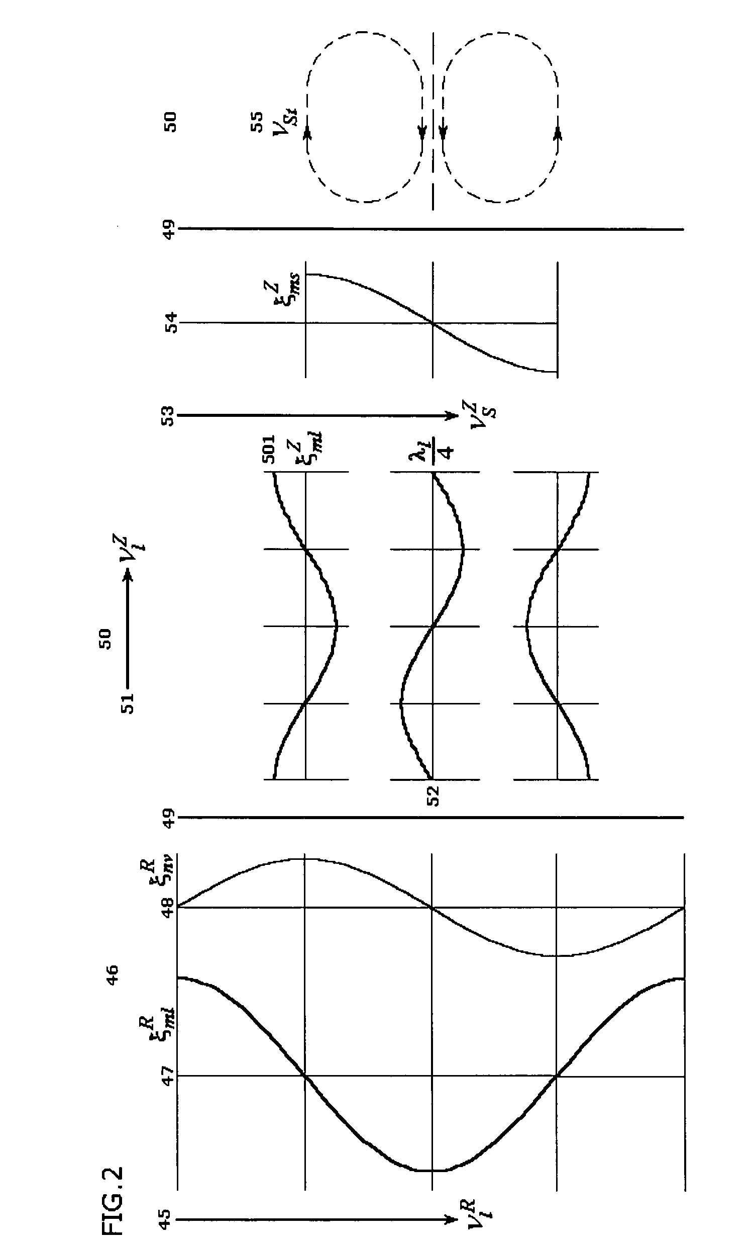
[0050] Present invention, with the purpose of increasing permeability of the well bore region of oil, gas and / or water wells proposes a method and device for stimulating said region with mechanical vibrations, with en end to promoting the formation of shear vibrations in said extraction zone due to the displacement of phase in the mechanical vibrations produced along the axis of the well, achieving alternately tension and pressure due to the superposition of the longitudinal and shear waves, and stimulating in this way the occurrences of mass transference processes within the well.

[0051] This last can be illustrated by the diagrams presented in FIG. 2, where the vector of oscillating velocity VRl (45) of longitudinal vibrations that propagate in the radiator (46), is directed along the axis of the radiator, while the amplitude distribution of vibratory displacements ξRml (47) of longitudinal vibrations also propagate along the radiator. In lieu of this, as a result of the Poisson e...


PUM


Abstract

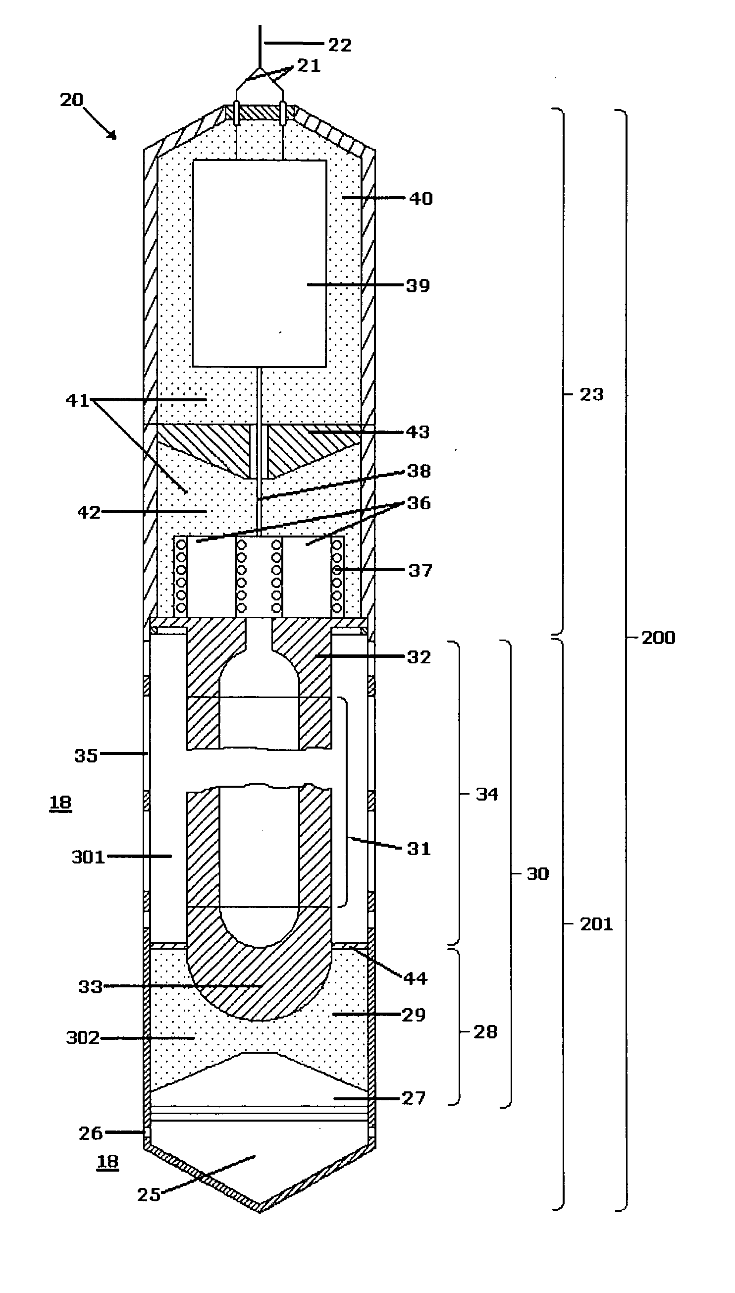
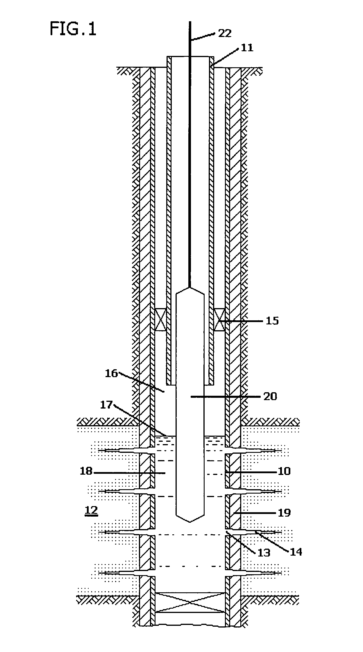
An electro acoustic device and related method for increasing the production capacity of wells that contains oil, gas and/or water is disclosed. The electro acoustic device is submerged in the well producing zone, and includes an electric generator, one or more electro acoustic transducers, and one or more wave guide systems (sonotrodes) that include radiators which transmit vibrations into the medium under treatment. The electro acoustic device produces vibrations that stimulate the occurrence of mass transfer processes within the well. According to one or more embodiments, shear vibrations are produced in the well bore region due to the phase displacement of mechanical vibrations produced along the axis of the well, achieving alternate tension and pressure due to the superposition of longitudinal and shear waves.

Description

FIELD OF APPLICATION [0001] Present invention is related to the oil industry, particularly an electro acoustic system and associated method for increasing the production capacity of oil wells and consists in applying mechanical waves in the interior of said wells. PREVIOUS STATE OF THE ART [0002] The productivity of oil wells decreases in time due to varied reasons. The two main causes have to do with the decrease in the relative permeability of the crude oil, thus decreasing its fluidity, and the progressive plugging of the pores of the reservoir in the well bore region due to accumulation of solids (clays, colloids, salts)that reduce the absolute permeability or interconnection of the pores. The problems associated to the aforementioned causes are: plugging of the pores by fine mineral particles that flow together with the fluid to be extracted, precipitation of inorganic crusts, paraffin and asphaltene decantation, clay hydration, invasion of mud solids and mud filtration, invasi...

Claims


Application Information

Patent Timeline
Patent Type & Authority Applications(United States)
IPC IPC(8): E21B28/00E21B43/00
CPCE21B43/003E21B28/00
Inventor ABRAMOV, OLEGABRAMOV, VLADIMIRGARRETON, ALFREDO ALEJANDRO ZOLEZZIROJAS, LUIS ORLANDO PAREDESPECHKOV, ANDREY
Owner SONOPLUS
Why Eureka
Try Eureka