
Intravascular filter with debris entrapment mechanism

a filter and debris technology, applied in the field of intravascular filtering apparatus and methods, can solve the problems of end-organ ischemia, heart attack, vascular occlusion,

Inactive Publication Date: 2005-01-13
MEDTRONIC INC
View PDF99 Cites 336 Cited by
  • Summary
  • Abstract
  • Description
  • Claims
  • Application Information

AI Technical Summary

Benefits of technology

[0007] A further object of the invention is to provide a filtering mechanism with greater ability to collect debris in the intravascular system of a patient to decrease the number of complications attributable to such debris.
[0010] Another still further object of the present invention is to provide a method for introducing a filtering device in the aorta downstream of the aortic valve to restrict the passage of emboli while allowing blood to flow through the aorta during cardiovascular procedures, and to entrap debris collected in the filter so as to prevent its escape during cardiac diastole or during manipulation, repositioning or removal of the device from the aorta.
[0011] With the above and other objects in view, as will hereinafter appear, there is provided apparatus for debris removal from the vascular system of a patient, said apparatus comprising: a filtering device having a proximal side and a distal side said filter being sized to allow blood flow therethrough and to restrict debris therethrough and said filter having a first given perimeter, wherein blood flow in a first direction passes from the proximal side to the distal side of the filtering device; an entrapment mechanism having a proximal side and a distal side, the entrapment mechanism forming a selective opening to allow debris and blood flow passage in the first direction from the proximal side to the distal side therethrough, the selective opening having a restriction mechanism to prevent debris passage in a second direction opposite to said first direction the selective opening having a second given perimeter, the first given perimeter and the second given perimeter being deployed within the vascular system so as to form a chamber between the distal side of the entrapment mechanism and the proximal side of the filtering device, wherein the entrapment mechanism allows blood flow and debris to pass therethrough in the first direction, the filtering device allows blood flow to pass therethrough in the first direction, the restriction mechanism prevents debris from passing back through said selective opening in a second direction opposite to the first direction and the chamber contains the debris received through the entrapment mechanism so as to prevent the escape of the debris therein by said filtering device in the first direction and said restriction mechanism in said second direction.
[0012] In accordance with another further feature of the invention there is provided a method for filtering and entrapping debris from the vascular system of a patient, the method comprising: providing apparatus for filtering and entrapping debris from the vascular system of a patient, the apparatus comprising: a filter device being sized to allow blood flow therethrough and to restrict passage of debris therethrough, and the filter device having a first given perimeter, a proximal side and a distal side; and wherein the filtering device captures debris carried in a first direction of blood flow from the proximal side to the distal side thereof on the proximal side of the filter device; an entrapment mechanism having a proximal side and a distal side, the entrapment mechanism including a selective opening to allow passage of blood and debris therethrough, the selective opening being configured to allow passage of blood and debris carried therein therethrough in the first direction of blood flow from the proximal side to the distal side of the entrapment mechanism, the selective opening having a restriction mechanism to prevent debris passage from the distal side to the proximal side of the entrapment mechanism in a second direction opposite to the first direction, the selective opening forming a second given perimeter, and the first given perimeter and the second given perimeter being deployed within the vascular system so as to form a chamber between the distal side of the entrapment mechanism and the proximal side of the filtering device; wherein the entrapment mechanism allows blood and debris carried therein therethrough in the first direction of blood flow, the filtering device allows blood therethrough in the first direction of blood flow, and the restriction mechanism prevents debris back through the selective opening in the second direction of blood flow opposite to the first direction of blood flow such that the chamber entraps the filtered debris received therein for debris removal from the vascular system of the patient; inserting said apparatus into the vascular system of the patient; allowing blood and debris carried therein to flow through the entrapment mechanism, and into the chamber; and removing the apparatus from the vascular system of the patient.

Problems solved by technology

Such debris, once free in the vascular system, may cause complications including vascular occlusion, end-organ ischemia, stroke, and heart attack.
There is a danger, however, that such debris may escape the filter mechanism during diastole or during filter removal.

Method used


Image

  • Intravascular filter with debris entrapment mechanism
  • Intravascular filter with debris entrapment mechanism
  • Intravascular filter with debris entrapment mechanism

Examples


Embodiment Construction

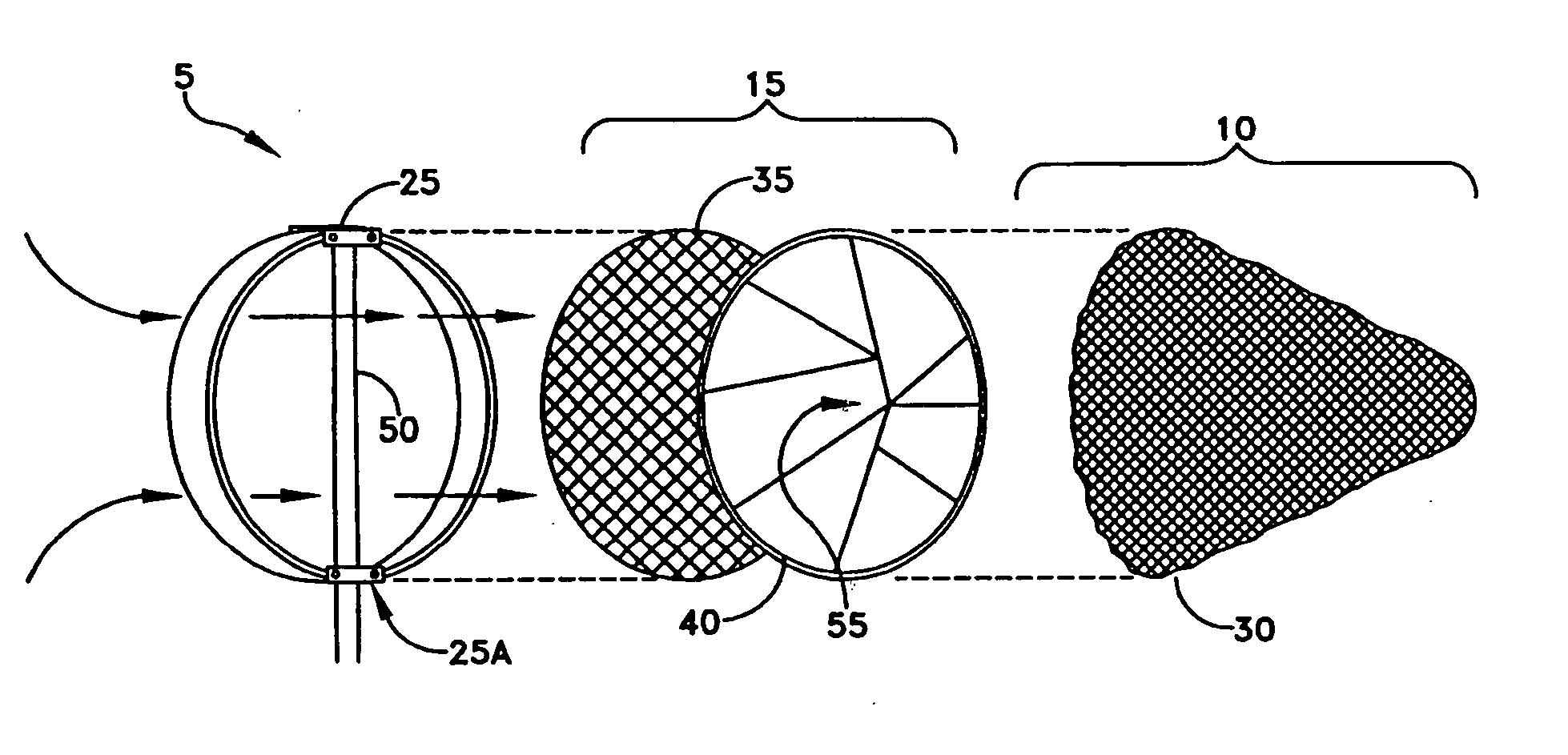
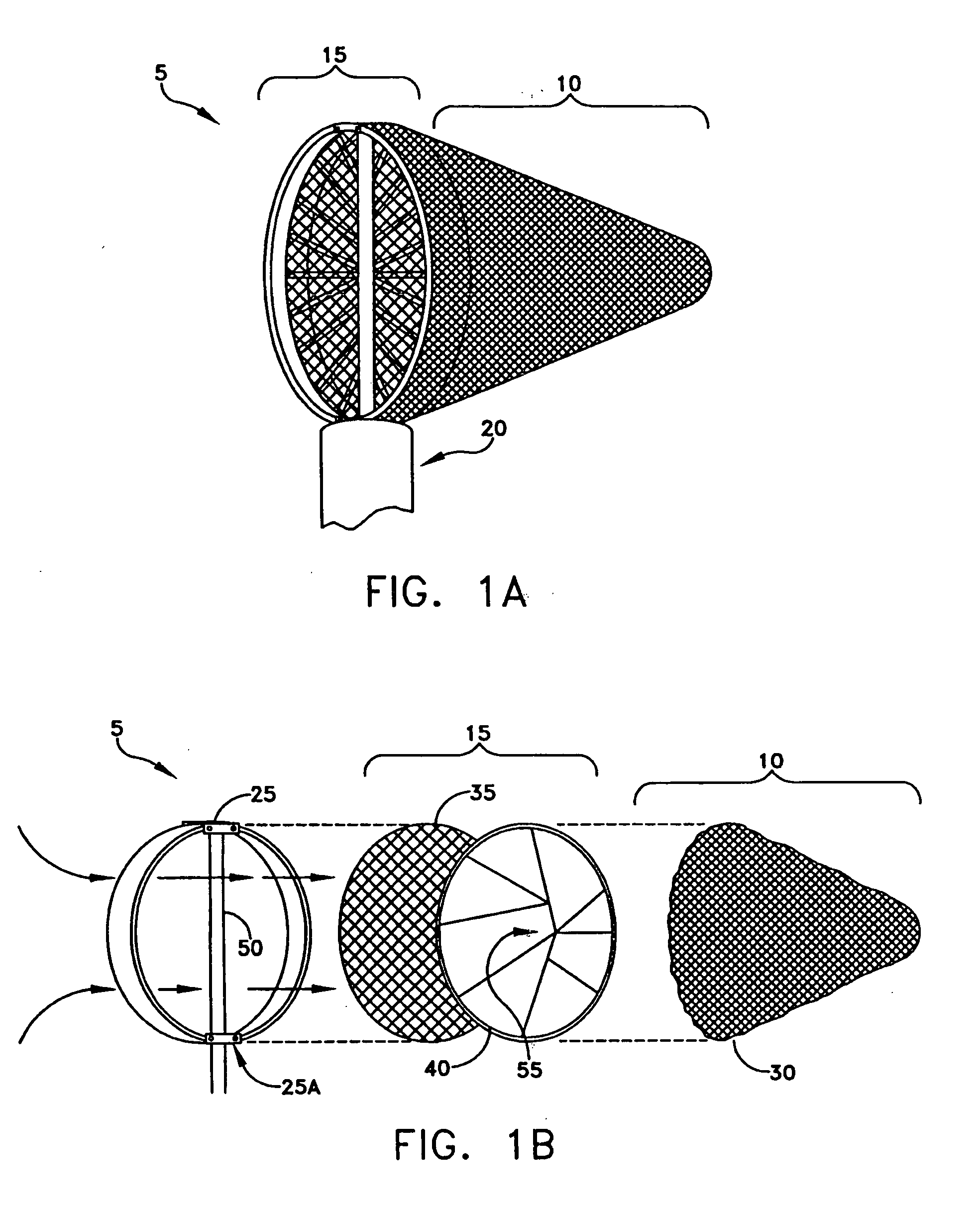
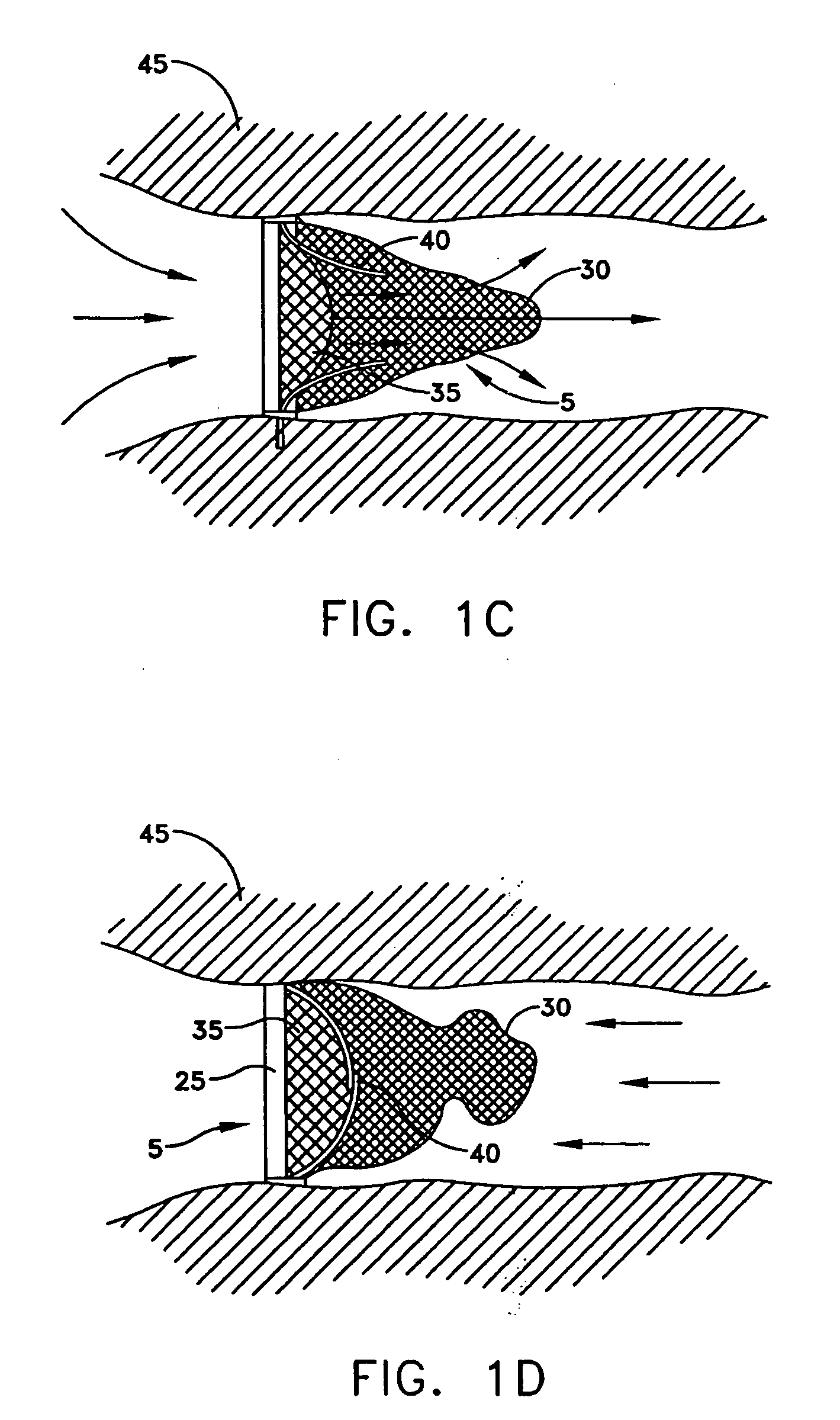
[0026] A filtration and entrapment apparatus 5 is shown in FIGS. 1A-5D for debris removal from the vascular system of a patient. Filtration and entrapment apparatus 5 generally includes a filter device 10 and an entrapment mechanism 15. Filtration and entrapment apparatus 5 can be used to filter emboli during a variety of intravascular or intracardiac procedures, including, but not limited to, the following procedures: vascular diagnostic procedures, angioplasty, stenting, angioplasty and stenting, endovascular stent-graft and surgical procedures for aneurysm repairs, coronary artery bypass procedures, cardiac valve replacement and repair procedures, and carotid endardarectomy procedures.

[0027] Now looking at FIGS. 1A-1D, a preferred embodiment of the present invention is shown with filtration and entrapment apparatus 5 as described herein below.

[0028]FIG. 1A depicts the profile of filtration and entrapment apparatus 5 in its fully deployed shape, with filter device 10 and entrapm...


PUM


Abstract

Apparatus for filtering and entrapping debris in the vascular system of a patient, the apparatus including a filter to allow blood to flow therethrough and to restrict passage of debris, wherein the filter captures debris carried in a first direction of blood flow. The apparatus further includes an entrapment mechanism which allows passage of debris and blood therethrough, in the first direction of blood flow and prevents debris passage in a second direction. The entrapment mechanism and filter allow blood and debris therethrough in the first direction of blood flow. The entrapment mechanism prevents debris flow in the second direction of blood flow. A method for filtering and entrapping debris in the vascular system includes inserting the apparatus into the vascular system, allowing blood and debris carried therein to flow through the entrapment mechanism, and removing the apparatus and accumulated debris from the vascular system.

Description

REFERENCE TO PENDING PRIOR PATENT APPLICATION [0001] This patent application claims benefit of pending prior U.S. Provisional Patent Application Ser. No. 60 / 215,542, filed Jun. 30, 2000 by Richard B. Streeter et al. for INTRAVASCULAR FILTER WITH DEBRIS ENTRAPMENT MECHANISM, which patent application is hereby incorporated herein by reference, and of pending prior U.S. Provisional Patent Application Ser. No. 60 / 231,101, filed Sep. 08, 2000 by Richard B. Streeter et al. for INTRAVASCULAR FILTER WITH DEBRIS ENTRAPMENT MECHANISM, which patent application is hereby incorporated herein by reference.FIELD OF THE INVENTION [0002] This invention relates to intravascular filtering apparatus and methods in general, and more particularly to apparatus and methods for filtering and irreversibly entrapping embolic debris from the vascular system during an intravascular or intracardiac procedure. BACKGROUND OF THE INVENTION [0003] Intracardiac and intravascular procedures, whether performed percutan...

Claims


Application Information

Patent Timeline
IPC IPC(8): A61F2/01
CPCA61F2/01A61F2002/018A61F2/013A61F2230/0067A61F2230/008A61F2230/0006
Inventor STREETER, RICHARD B.LAMBRECHT, GREGORY H.LIDDICOAT, JOHN R.MOORE, ROBERT KEVINDAVENPORT, TODD F.
Owner MEDTRONIC INC
Learn More