High linearity doherty communication amplifier with phase control

a communication amplifier and phase control technology, applied in the direction of amplifier combinations, amplifier modifications to reduce non-linear distortion, sustainable buildings, etc., can solve the problems of reducing the efficiency of the overall system, consuming the most power of the radio frequency (rf) power amplifier, and reducing the talk time, so as to achieve the effect of managing the non-linearity characteristics of the power amplifier

Inactive Publication Date: 2005-01-20
AVAGO TECH WIRELESS IP SINGAPORE PTE +1
View PDF17 Cites 118 Cited by
  • Summary
  • Abstract
  • Description
  • Claims
  • Application Information

AI Technical Summary

Benefits of technology

[0012] In another embodiment of the invention, a baseband modem chipset generates the voltage control signal according to signals received from the base station. Specifically, when the required output power level of the power amplifier is in a low output power range, a control voltage in a first state is applied to the peak amplifier so that the power amplifier is operated in a Doherty mode and, in a high output power range, a control voltage in a second state is applied to the peak amplifier so as to sufficiently manage non-linearity characteristics of the power amplifier.

Problems solved by technology

In a conventional mobile handset, the Radio Frequency (RF) power amplifier consumes most of the power of the overall mobile handset system.
Thus, the RF power amplifier having a low efficiency typically results in degradation of the efficiency for the overall system, and accordingly reduces the talk time.
However, typical Doherty-type power amplifiers include phase delay circuitry and output matching circuitry comprised of bulky, space-consuming transmission lines.
But, when the power amplifier operates within a high output power range, the peak amplifier is active and may introduce nonlinearity into the overall power amplifier since the peak amplifier is biased as a highly nonlinear class B or class C amplifier.
However, as described above, because the Doherty-type power amplifier comprises a carrier amplifier and a peak amplifier that operate with each other, the Doherty-type power amplifier in practice does not satisfy the linearity specification (e.g., in terms of phase or amplitude of gain characteristics) over the entire output power range where high efficiency is maintained.
In summary, in the above-mentioned Doherty-type power amplifier in the related art, the linearity characteristics of such a power amplification device are difficult to predict, which makes it difficult to improve such linearity characteristics because the peak amplifier is biased at a relatively constant, low DC current level, such as a current to set the peak amplifier as a class B or C amplifier.
In addition, typical Doherty-type power amplifiers of the related art comprise bulky transmission line circuitry that may impede integration of the power amplifier into mobile handsets, unless size issues associated with power amplifier design are further addressed.

Method used


Image

  • High linearity doherty communication amplifier with phase control
  • High linearity doherty communication amplifier with phase control
  • High linearity doherty communication amplifier with phase control

Examples


Embodiment Construction

[0047] Hereinafter, a detailed description will be given with reference to the attached drawings as to an exemplary power amplifier in a mobile handset in accordance with various embodiments of the invention.

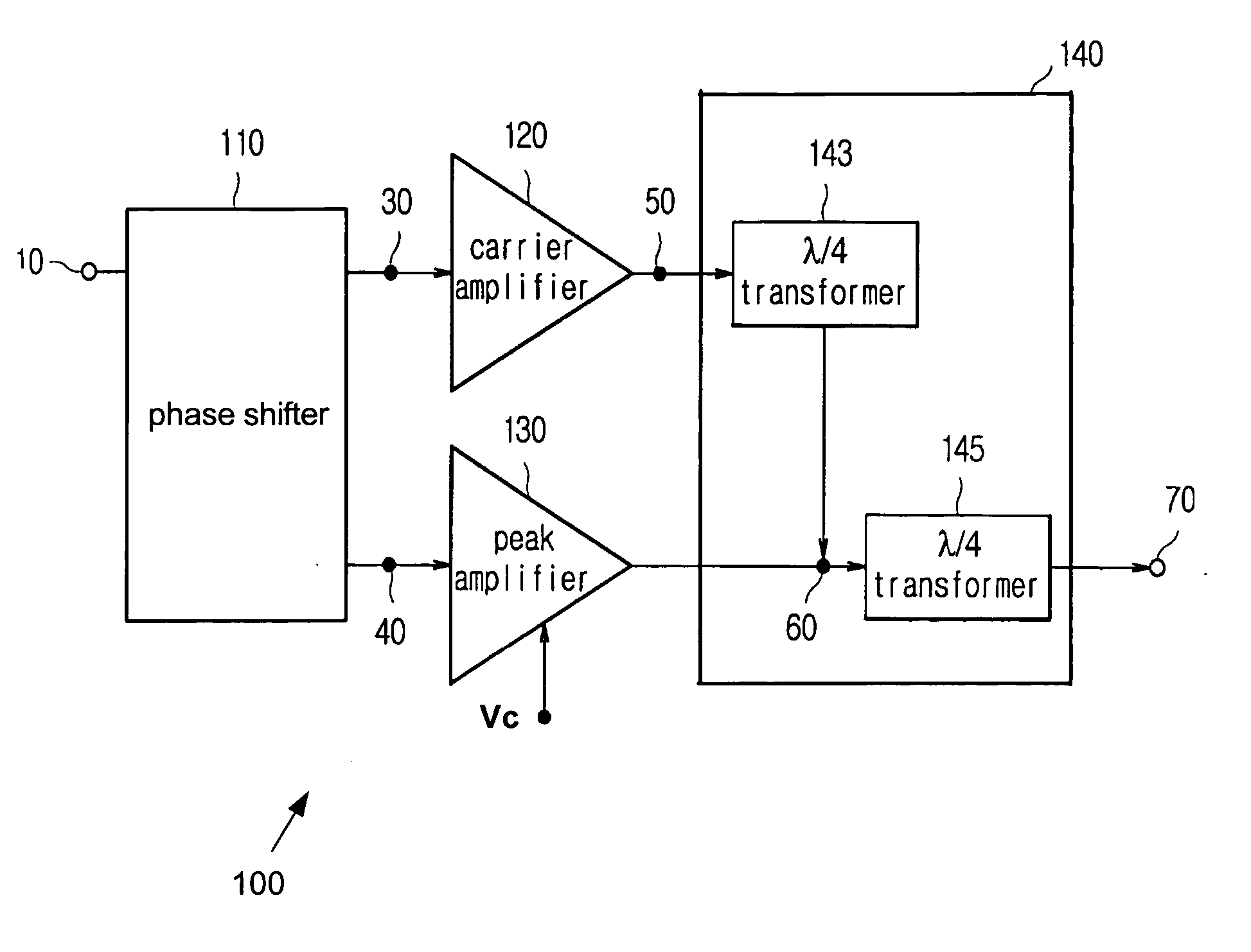
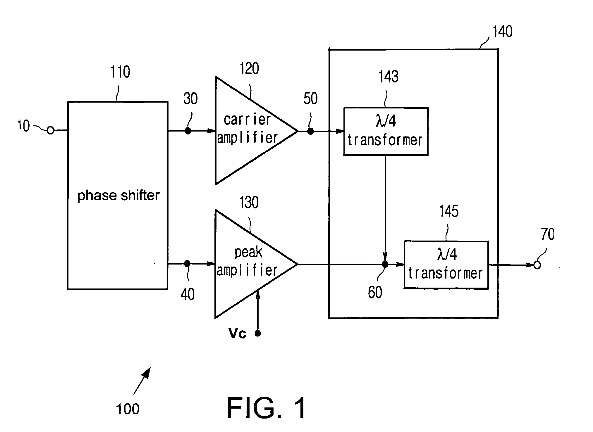
[0048]FIG. 1 illustrates an exemplary power amplifier 100 in a mobile handset in accordance with a specific embodiment of the invention. Power amplifier 100 comprises a phase shifter 110, a carrier amplifier 120, a peak amplifier 130, and an output matching unit 140. Phase shifter 110 distributes certain input powers to carrier amplifier 120 and peak amplifier 130, minimizes interference between carrier amplifier 120 and peak amplifier 130 and transmits signals in such a manner that the phase of input signal of peak amplifier 130 is 90° (λ / 4) delayed from the phase of input signal of carrier amplifier 120. Accordingly, phase shifter 110 compensates for a later processing of output signals from carrier amplifier 120 and peak amplifier 130 by output matching unit 140 by generatin...


PUM


Abstract

A high linearity Doherty power amplifier with phase delay generation and control via passive and active components. In one embodiment, phase delay generation and control is implemented by an active phase shifter comprising a lower differential unit for generating a first differential output signal, an upper differential unit for generating a second differential output signal, and a phase control unit for tuning a phase difference between the first and second differential output signals within a phase tolerance. In addition, to improve efficiency and linearity characteristics, the power amplifier receives a voltage control signal to bias a supplemental amplifier so that the power amplifier operates in a Doherty mode in a low output power range and in a non-Doherty mode in a high output power range.

Description

RELATED APPLICATIONS [0001] This application is a continuation-in-part application of U.S. patent application Ser. No. 10 / 432,553 filed on May 21, 2003 entitled “Power Amplification Apparatus of Portable Terminal,” which is hereby incorporated by reference. The U.S. patent application Ser. No. 10 / 432,553 is a National Stage application for and claims priority to International Application No. PCT / KR02 / 00163, filed Feb. 4, 2002, which claims priority to Korean Utility patent Application No. 2002-5924, filed on Feb. 1, 2002, both of which are incorporated by reference herein for all purposes.TECHNICAL FIELD [0002] The invention relates to a power amplification circuit for use in wireless communication technologies, and more particularly to a power amplification circuit in a mobile handset. BACKGROUND ART [0003] As mobile handsets used for wireless communication services are becoming smaller and lighter, battery size is also decreasing. Consequently, the effective talk time (i.e., trans...

Claims


Application Information

Patent Timeline
Patent Type & Authority Applications(United States)
IPC IPC(8): H03F3/68H03F1/02H03F1/07H04B1/04
CPCH03F1/0205H03F1/0233H03F1/0288H03F1/32Y02B60/50H03F2200/198H03F2200/423H03F2200/543H04B2001/045H03F2200/102H03F1/02H03F3/24H04B1/04
Inventor KWON, YOUNGWOOKIM, JUNGHYUN
Owner AVAGO TECH WIRELESS IP SINGAPORE PTE
Why Eureka
Try Eureka