
Touch sensor with non-uniform resistive band

a resistive band and touch sensor technology, applied in the direction of instrumentation, pulse technique, keyboard-like device coding, etc., can solve the problems of unsuitable touch region, undesirable region around the electrode, exacerbate poor crossing, etc., to achieve the effect of reducing the fractional width of the electrically conductive elements, reducing the number of electrodes, and improving the quality of the touch sensor

Inactive Publication Date: 2005-01-20
ELO TOUCH SOLUTIONS INC
View PDF19 Cites 108 Cited by
  • Summary
  • Abstract
  • Description
  • Claims
  • Application Information

AI Technical Summary

Benefits of technology

The touch sensor further comprises a resistive band that frames the touch region. The resistive band is an intermediate resistive band in that it has a resistivity that is between the resistivity of the electrodes and the resistivity of the touch region. The resistive band is continuous or quasi-continuous along at least a portion of its length, preferably the entire length of the band. In this manner, the outer edges of the workable touch region extends all the way, or very close, to the band, thereby maximizing the effective touch region.
In accordance with a first aspect of the present inventions, the touch sensor comprises band segments, at least one of which has a linear resistance that varies along its length. For example, each band segment can have a linear resistance that is smallest in the center region of the band segment, but increases along the length of the band segment towards the ends of the band segment. Computer simulations have shown that the electrical field strength in the corners is increased, thereby reducing the errors in these corners.
Although the present invention should not be so limited in its broadest aspects, the use of an appropriate intermediate resistive band, especially if it has at least one band segment with a non-uniform linear resistance, will improve the topological equivalence within the corner regions, thereby making the algorithm modification process simpler.
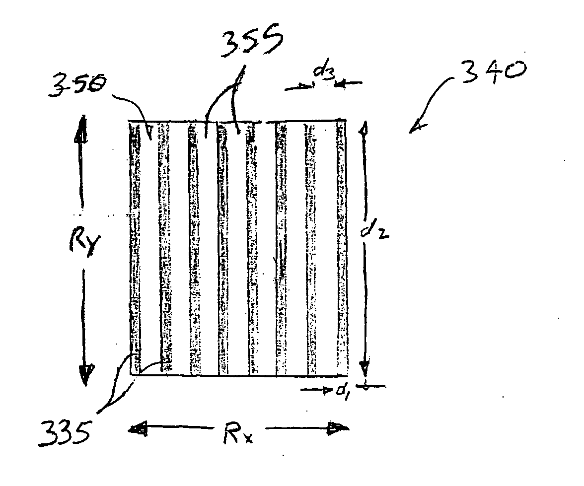
In accordance with a separate third aspect of the present inventions, at least one band segment comprises a continuous resistive background material and an array of electrically conductive elements disposed along at least a lengthwise portion of the band segment(s)over the background material. The conductive elements have a resistivity that is lower than the resistivity of the background material. Although the present invention should not be so limited in its broadest aspects, the addition of the conductive elements allows the linear resistance of the band to be more easily controlled and manufactured.
In one preferred embodiment, the touch region is formed by the background material, which simplifies the manufacturing process. If the resistance ratio, is relatively low, however, the background material can have a resistivity that is between the resistivity of the electrodes and the resistivity of the touch region, so that the fractional width of the electrically conductive elements can be kept well below unity.
In accordance with a separate fourth aspect of the present inventions the resistive touch region has a non-rectangular geometry. The non-rectangular geometry, can be, e.g., triangular, pentagonal, or hexagonal. The non-rectangular geometry can either be planar or non-planar. A set of electrodes is electrically coupled to the touch region for generating non-linear voltage gradients over the touch region. Notably, many touch regions with non-rectangular geometries will have worse topological equivalence than that in touch regions with rectangular geometries. As such, the use of an intermediate resistive band can increase this topological equivalence. The band may have a substantially uniform linear resistance for ease of manufacturability, or if greater improvement in topological equivalence is desired, the band can have a substantially non-uniform resistance. As with rectangular sensors, the resistance ratio can be selected to balance the needs of power efficiency and ease of topological mapping.

Problems solved by technology

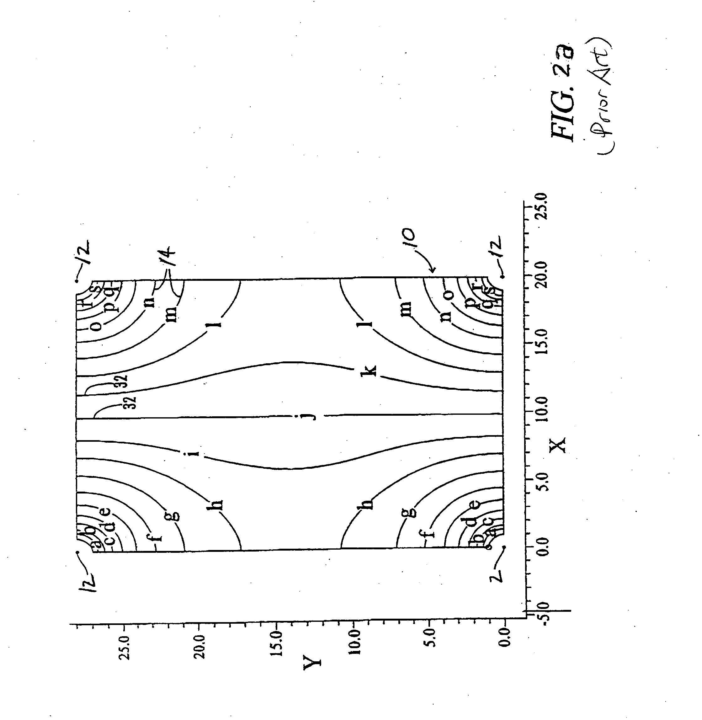
In the vicinity of the electrodes 12, however, there remains a problem of uniqueness.
This results in regions around the electrodes that are not suitable as a touch region—an undesirable effect in today's highly competitive touchscreen market.
This poor-crossing problem is exacerbated by noise or uncertainty in the measurement of the voltage potentials, which tends to blur the intersection points of equipotential lines, such that a unique position cannot be determined within the poor-crossing region.
Thus, the poor-crossing problem may exist even if the equipotential pair intersects—albeit at shallow angles.
Such cases generally tend to show the same problems of uniqueness in the poor-crossing regions.
Various electrode configurations that are not circular, such as L configurations, can be visualized to decrease the size of these poor-crossing regions, but the problem still exists.
Unless the substrate resistivity is very large (greater than a few thousand ohms / square), such low β designs lead to touchscreens of less than a few ohms resistance, drawing too much power.
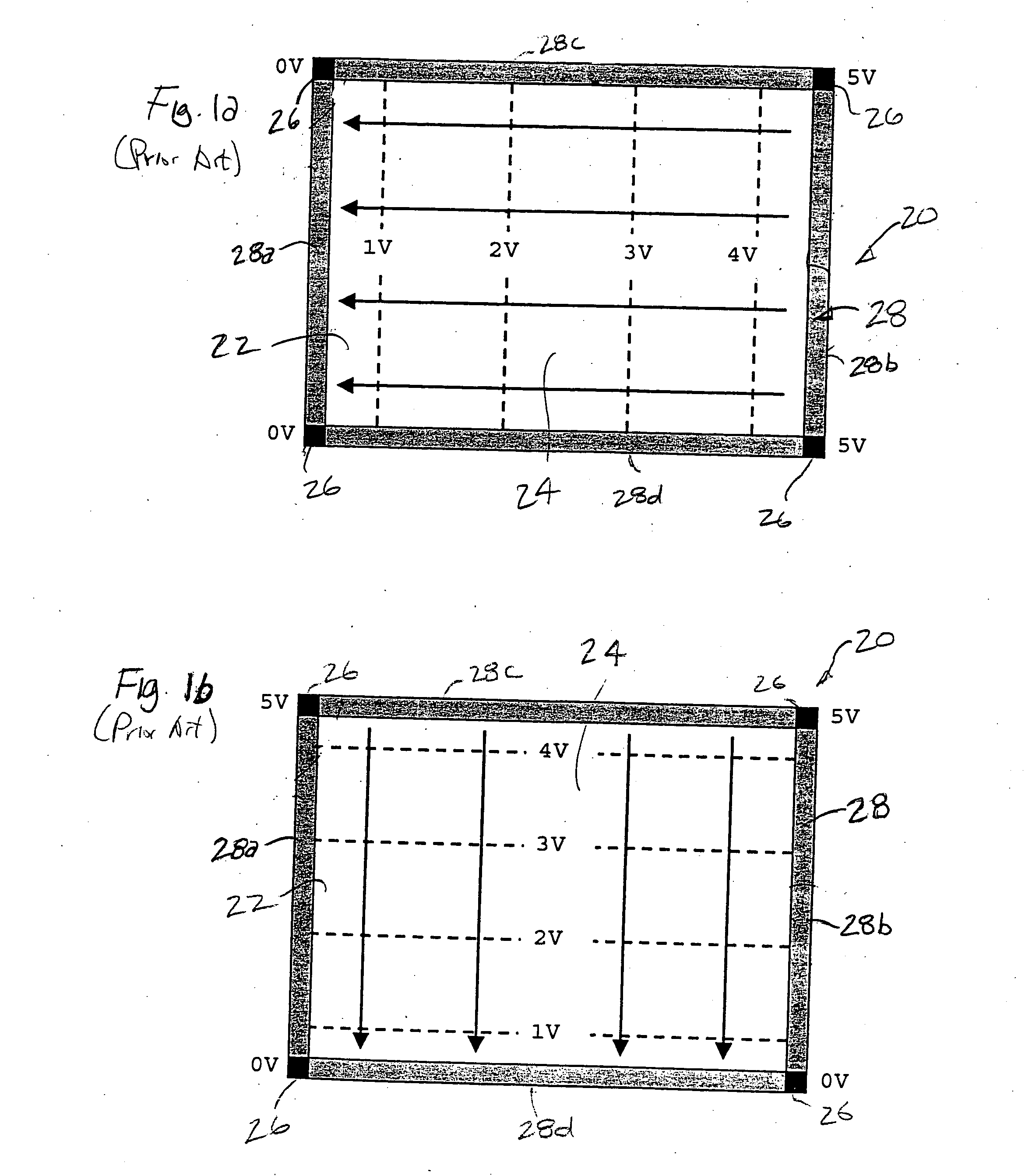
However, if the resistance ratio, becomes very high (β>>1), while the touchscreen power efficiency approaches 100%, the equipotentials tend to circle around the electrodes for both directions of excitation, as illustrated in FIG. 2a and 2b, thereby forming poor-crossing regions near the electrodes.
Even with elaborate topological mapping methodologies, the coordinates near the electrodes are difficult to determine uniquely.
Excessive border width, however, is very undesirable from the point-of-view of compactness.

Method used


Image

  • Touch sensor with non-uniform resistive band
  • Touch sensor with non-uniform resistive band
  • Touch sensor with non-uniform resistive band

Examples


Embodiment Construction

Referring to FIG. 4, a resistive touchscreen system 100 constructed in accordance with a preferred embodiment of the present invention is described. The touchscreen system 100 generally comprises a touchscreen 105 (i.e., a touch sensor having a transparent substrate), controller electronics 110, and a display (not shown). The touchscreen system 100 is typically coupled to a host computer 115. Generally, the controller electronics 110 sends excitation signals to the touchscreen 105 and receives analog signals carrying touch information from the touchscreen 105. Specifically, the controller electronics 110 establishes a voltage gradient across the touchscreen 105. The voltages at the point of contact are representative of the position touched. The controller electronics 110 digitizes these voltages and transmits these digitized signals, or touch information in digital form based on these digitized signals, to the host computer 115 for processing.

Referring now to FIG. 5, the touchsc...


PUM


Abstract

The present inventions are directed to touch sensors with improved topological equivalence between an equipotential space and a Cartesian space to which the equipotential space will be mapped. The touch sensor comprises a substrate with a touch region, and a set of electrodes that are electrically coupled to the touch region. The touch sensor further comprises a plurality of resistive band segments that frames the touch region. The electrodes are located between the resistive band segments. Each resistive band segment has a resistivity that is intermediate between the resistivity of the electrodes and the resistivity of the touch region, thereby providing a transition between the low resistivity electrodes and the high resistivity touch region, and improving the topological equivalence within the corners of the touch region. At least one of the band segments has a non-uniform linear resistance to provide further improvement to the topological equivalence.

Description

FIELD OF THE INVENTION The field of the present invention relates to touch sensor technology, and more particularly to resistive and capacitive touch sensor technology. BACKGROUND OF THE INVENTION Touch sensors are transparent or opaque input devices for computers and other electronic systems. As the name suggests, touch sensors are activated by touch, either from a user's finger, or a stylus or some other device. Transparent touch sensors, and specifically touchscreens, are generally placed over display devices, such as cathode ray tube (CRT) monitors and liquid crystal displays, to create touch display systems. These systems are increasingly used in commercial applications such as restaurant order entry systems, industrial process control applications, interactive museum exhibits, public information kiosks, pagers, cellular phones, personal digital assistants, and video games. The dominant touch technologies presently in use are resistive, capacitive, infrared, and acoustic te...

Claims


Application Information

Patent Timeline
IPC IPC(8): G06F3/033G06F3/045G06F3/048
CPCG06F3/0488G06F3/045G06F2203/04113
Inventor HURST, G. SAMUELRITCHIE, R.H.WARMACK, ROBERT J.BOULDIN, DONALD W.KENT, JOEL C.
Owner ELO TOUCH SOLUTIONS INC
Learn More