Macro-pixel image rendering apparatus and associated methods

a technology of image rendering and macropixels, applied in image data processing, printing, instruments, etc., can solve the problems of limiting dark color saturation and linearity, limiting the possibilities, and steady cyclic tint and brightness noise, so as to achieve less ink spot edges, less ink depth, and brighter images.

Active Publication Date: 2005-01-20
TECH PHOTOGRAM
View PDF10 Cites 7 Cited by
  • Summary
  • Abstract
  • Description
  • Claims
  • Application Information

AI Technical Summary

Benefits of technology

[0007] An additional advantage of the present invention, specially when applied to animated, interactive and/or auto-stereoscopic 3D lenticular printing, is the possibility to obtain brighter images, delivering more white surface light reflection (or transmission, for backlit image) than any other full color ink printing process, without sacrifice of color depth, gamut range or linearity. For silk-screen applications, the image rendering method disclosed herein is ideal for print resistance to washing and other causes of wear, because it exposes less ink spot edges to the effects of detergent and friction.
[0008] A low and constant effective dot gain is one of the factors that gives the present invention more color precision and depth than stochastic and FM screenings, while producing much less noise.
[0009] By choosing the image rendering method described herein, e.g., color reproduction printing instead of photographic reproduction, considerable cost reductions are possible while obtaining relatively comparable results, in term of quality. Of course, the color gamut is not the same (Red, Green, Blue (RGB) vs. Cyan, Magenta, Yellow, Key (CMYK)), but more basic color inks may be added to extend it far beyond the photographic process limits.
[0010] All these innovations can b

Problems solved by technology

While it limits the possibilities of visible moiré effect, it also causes steady cyclic tint and brightness noise, and limits dark color saturation and linearity.
Stochastic and/or FM

Method used


Image

  • Macro-pixel image rendering apparatus and associated methods
  • Macro-pixel image rendering apparatus and associated methods
  • Macro-pixel image rendering apparatus and associated methods

Examples


Embodiment Construction

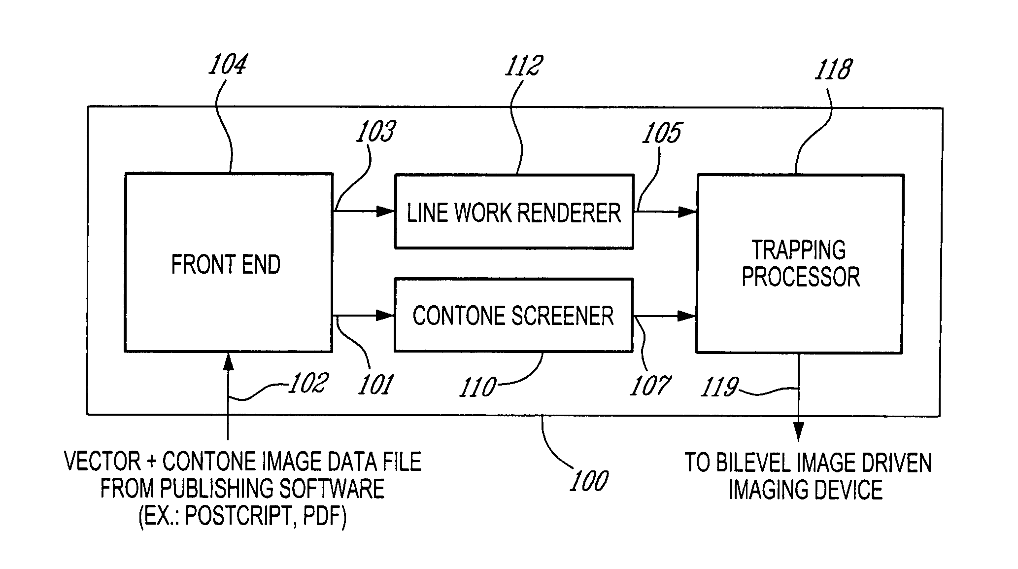
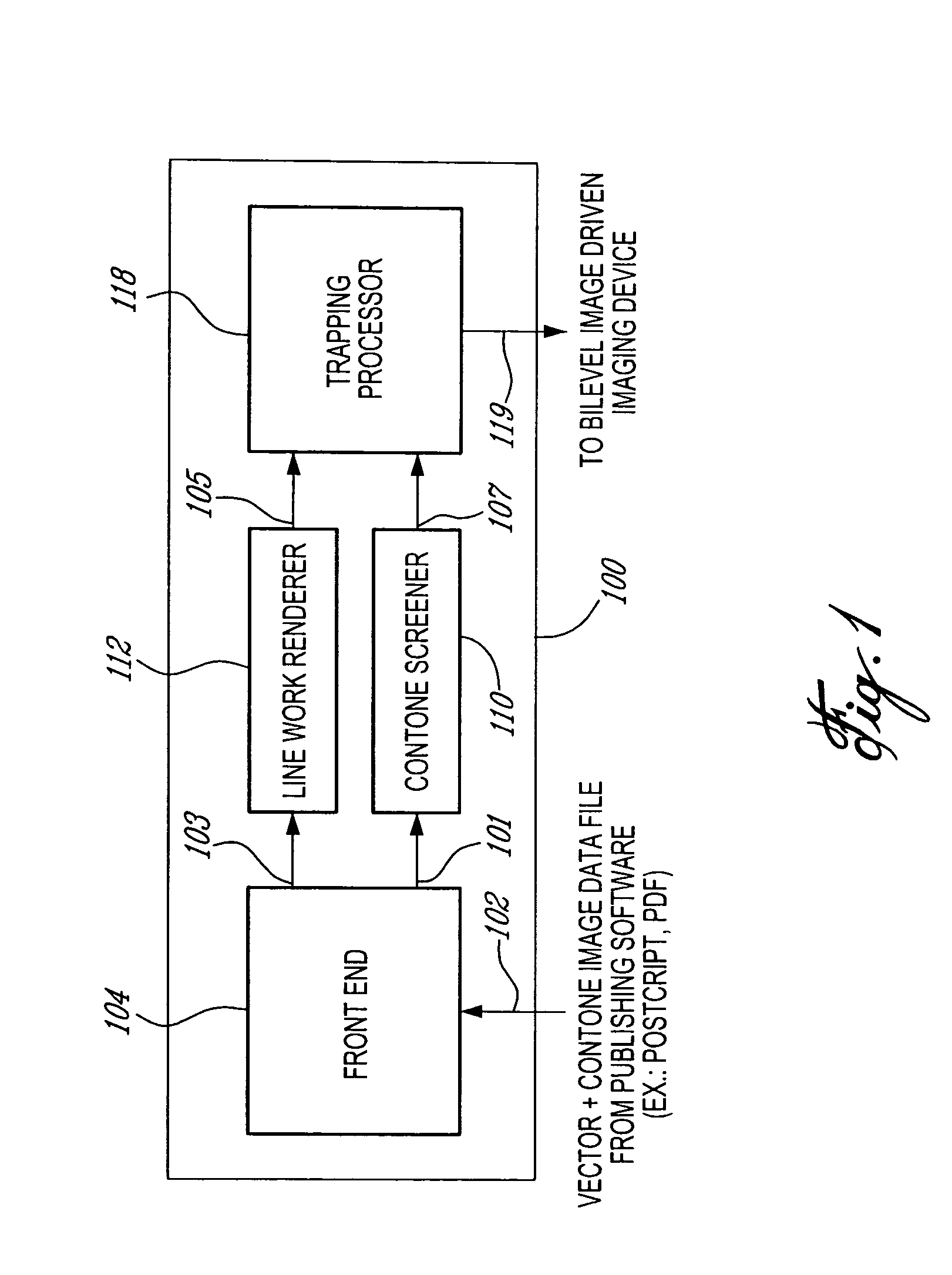
[0024]FIG. 1 illustrates a standard Raster Image Processor (RIP) 100 block diagram and its data flow from the input 102 of the RIP software front end 104 to the output 119 of merge and trapping processor 118 which is fed to a bilevel image driven imaging device (not shown). In a preferred embodiment, the process described herein takes place in the contone screener 110.

[0025] As shown in FIG. 1, image files containing composition of color separated (usually CMYK) vectorized drawings, texts, fonts and / or contone pictures, coming from a publishing software in the form of Postscript, PDF or other popular electronic publishing format, are loaded (input 102) in the RIP front end 104. There, the file is interpreted and separated in its line work part 103 (vector based drawing and text) and its color separated contone part 101, and these parts (101 and 103) are fed to the line work renderer 112 and the contone screener 110 respectively. The line work renderer 112 and the contone screener 1...


PUM


Abstract

A macro-pixel used in an image rendering process for forming an image using a matrix of macro-pixels. The macro-pixel comprises a plurality of rectilinear parallel rows. All rows extend across the matrix in the same direction and each one of the rows is capable of at least partially adopting at least one of a color state and an off state. The on state includes the presence of color while the off state includes the absence of color. The on state comprises non-key and/or key colors. The non-key colors can be cyan, magenta, yellow, and/or any other color while the key color is normally black. The macro-pixel also includes columns formed by micro-pixels which may be turned on in a predetermined order. The predetermined order permits maximum distance between rows used for key colors and rows used for non-key colors.

Description

FIELD OF THE INVENTION [0001] The present invention relates to the field of processes used for image rendering. More specifically, the present invention is concerned with a macro-pixel image rendering apparatus and methods that may be used in printing processes. BACKGROUND OF THE INVENTION [0002] Since the beginning of full color lithographic offset printing, the concept of using different screen angle for each color has been applied to deal with press imperfections causing skew and displacement of basic colors, relative to each other. While it limits the possibilities of visible moiré effect, it also causes steady cyclic tint and brightness noise, and limits dark color saturation and linearity. Stochastic and / or FM screening methods solve the moiré problem, but add random tint, brightness noise and non-linearity, while increasing dot gain by multiplying the amount of outer edges of dot surface. [0003] Therefore, in spite of the efforts in the field, there is a need for improved mac...

Claims


Application Information

Patent Timeline
IPC IPC(8): H04N1/52H04N1/58
CPCH04N1/52G06F15/00
Inventor RICHER, PAUL
Owner TECH PHOTOGRAM
Why Eureka
Try Eureka