System and method for detecting faults in an aircraft electrical power system

a technology of electrical power system and aircraft, which is applied in the field of system and method for detecting faults in aircraft electrical power system, can solve the problems of not being able being unable to provide fault monitoring of devices or power-consuming loads, etc., to achieve reliable indication and detection

Inactive Publication Date: 2005-01-20
KOHLMEIER BECKMANN CARSTEN +1
View PDF9 Cites 19 Cited by
  • Summary
  • Abstract
  • Description
  • Claims
  • Application Information

AI Technical Summary

Benefits of technology

[0023] It is a significant advantage of the invention, that a fault of a power-consuming component or load that has a very low power consumption can still be reliably indicated and detected, without requiring additional signal lines or the like between the monitored load and the power distribution center. The only connection between the power distribution center and the sub-system power unit is the existing power connection through a power conductor line or power bus. Since ev...

Problems solved by technology

Although the use and functionality of databus systems is ever-increasing in aircraft, there are still many devices and particularly power-consuming loads that are simply connected directly to the aircraft power supply grid through conventional switching devices and the like, e.g. being connected via a power distribution center to the main power bus.
When these power connections are carried out via simple conventional conductors and switching circuits, it is not possible to provide a fault monitoring of the devices or power-consuming loads.
However, the lower limit or threshold of a detectable current variation in the power distribution center is generally greater than the current v...

Method used


Image

  • System and method for detecting faults in an aircraft electrical power system
  • System and method for detecting faults in an aircraft electrical power system
  • System and method for detecting faults in an aircraft electrical power system

Examples


Embodiment Construction

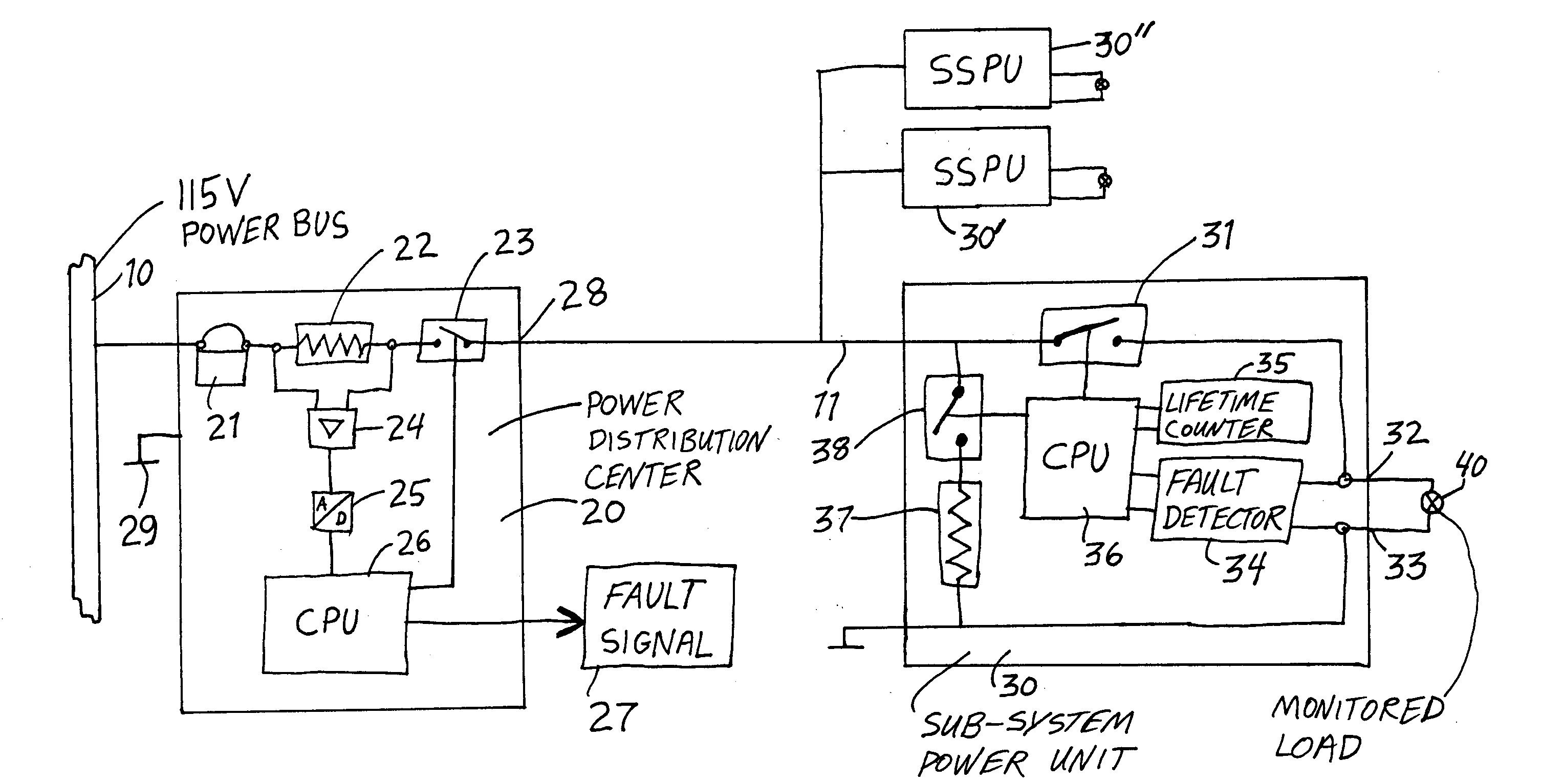
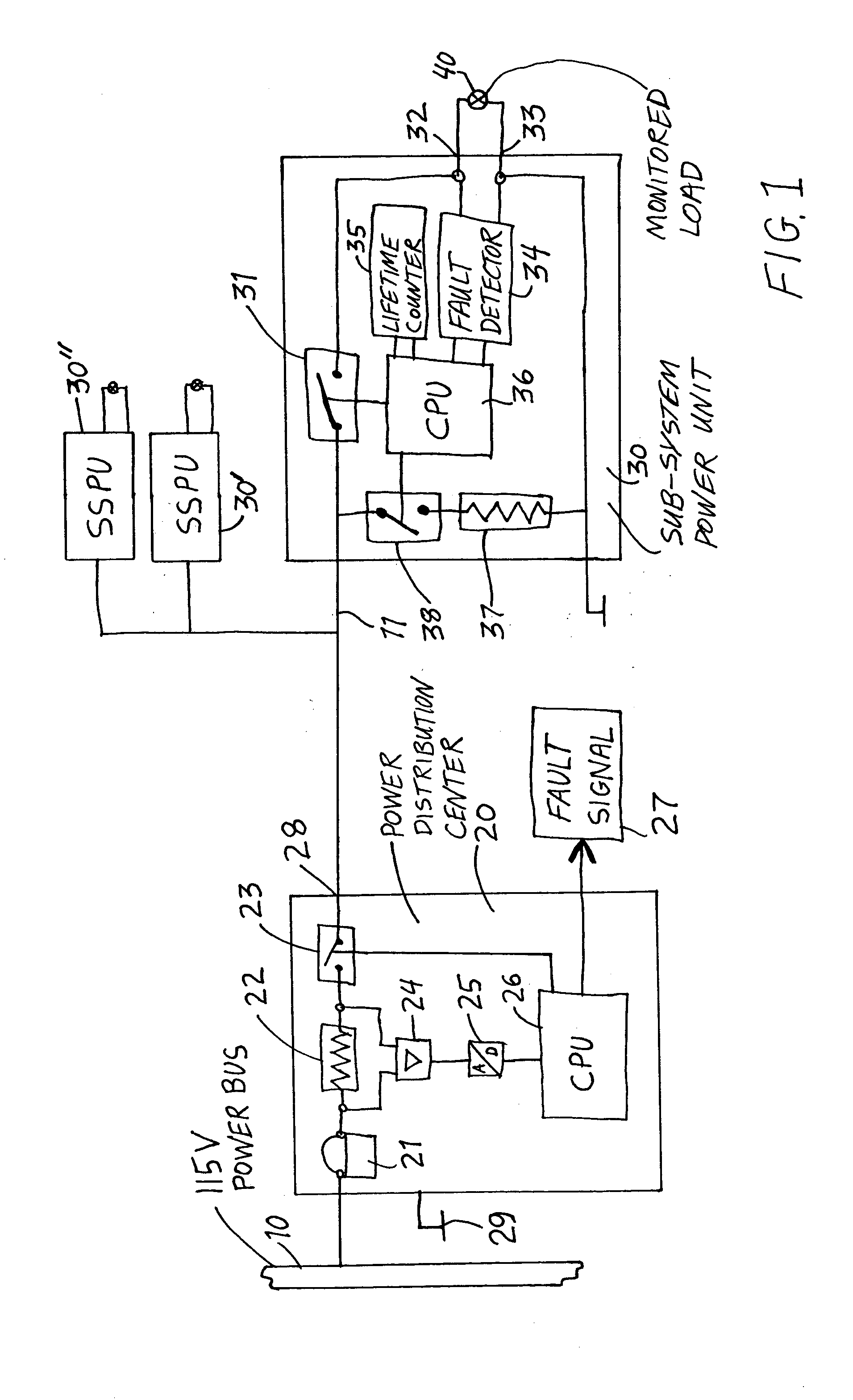
[0030] As schematically illustrated in FIG. 1, an electrical power system in an aircraft according to the invention includes a main electrical power bus 10, a power distribution center 20 connected to the power bus 10, and one or more sub-system power units 30, 30′ and 30″ connected via a sub-system power conductor or bus 11 to the power distribution center 20. A monitored electrical load 40 is connected to the power terminals 32 and 33 of the sub-system power unit 30 so as to be powered thereby.

[0031] The monitored load 40 includes one or more individual power-consuming components or devices, such as an individual lightbulb or a group of lightbulbs connected in series or parallel. The term “lightbulb” includes any electrically powered light source, such as an incandescent lightbulb, a fluorescent lightbulb, a light emitting diode (LED), a xenon flash tube, a high intensity discharge (HID) light source, or the like. The monitored load 40 may further include additional consumable pa...


PUM


Abstract

An aircraft electrical power system includes a monitored load (e.g. group of lightbulbs) connected through a sub-system power unit and a power distribution center to a power bus. A current monitor of the power distribution center is able to detect a total failure of the sub-system power unit and its connected monitored load, but is not able directly to detect the failure of a single load component (e.g. single lightbulb). The sub-system power unit includes a fault detector able to detect a fault or failure of a single load component (e.g. single lightbulb) in the monitored load. When the fault detector detects such a fault, the sub-system power unit generates a modulated current signal in the current drawn by the sub-system power unit, with a magnitude greater than the detection threshold of the power distribution center, which thus recognizes the detected fault based on the modulated current signal.

Description

PRIORITY CLAIM [0001] This application is based on and claims the priority under 35 U.S.C. §119 of German Patent Application 103 32 925.0, filed on Jul. 19, 2003, the entire disclosure of which is incorporated herein by reference. FIELD OF THE INVENTION [0002] The invention relates to both a system and a method for detecting faults, such as open circuits, short circuits, burned-out bulbs, and the like, in an electrical power system of an aircraft. BACKGROUND INFORMATION [0003] An electrical power supply grid or distribution system in a modern aircraft typically includes one or more power generators or sources connected to a main power bus to supply electrical power to the bus, and one or more power distribution centers connected to the power bus to distribute the available electrical power to various power-consuming sub-systems. The power-consuming sub-systems, for example, include galley ovens, galley water heaters, galley coffee makers, cabin lighting systems, exterior lighting sy...

Claims


Application Information

Patent Timeline
IPC IPC(8): B64D11/00B64D47/02H02H7/00H02J13/00
CPCH02J13/0024Y02E60/7823Y04S40/122H02J13/00009Y02E60/00Y04S40/121
Inventor KOHLMEIER-BECKMANN, CARSTENKESSLER, JENS
Owner KOHLMEIER BECKMANN CARSTEN
Why Eureka
Try Eureka