Tunable dispersion compensator and method for tunable dispersion compensation

Inactive Publication Date: 2005-01-20
NEC CORP
View PDF9 Cites 18 Cited by
  • Summary
  • Abstract
  • Description
  • Claims
  • Application Information

AI Technical Summary

Benefits of technology

[0017] It is an object of the present invention to provide a tunable dispersion compensator and a

Problems solved by technology

As the transmission rate is increased, a light waveform deteriorates due to chromatic dispersion in an optical fiber.
This causes a problem that the size of the equipment carrying out compensation of chromatic dispersion increases.
Furthermore, since the DCF has quite a large transmission loss of an optical signal, an expensive light amplifier is required to compensate for the transmission loss.
Furthermore, since the DCF has a small core diameter, the optical signal is trapped in a narrow are

Method used


Image

  • Tunable dispersion compensator and method for tunable dispersion compensation
  • Tunable dispersion compensator and method for tunable dispersion compensation
  • Tunable dispersion compensator and method for tunable dispersion compensation

Examples


Example

[0052] Then, the basic structure of the first mode filter of the first embodiment of the present invention will be explained.
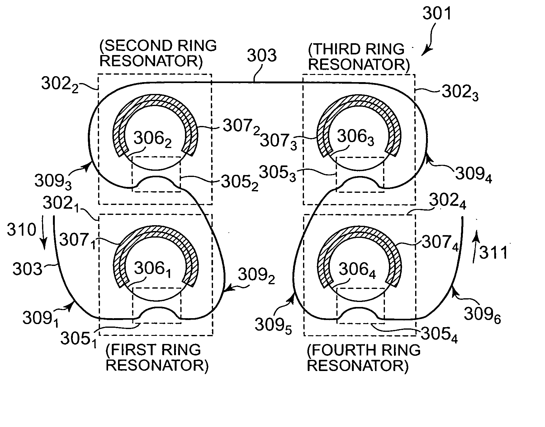
[0053]FIG. 7 shows a structure of the first mode filter 2041 according to the first embodiment. In the first mode filter 2041, the width D1 of the linear waveguide 203 through which an optical signal is transmitted gradually narrows from the area close to the entrance toward the central area down to a width D2 at the center. Then, the width of the linear waveguide 203 gradually extends from this center toward the exit up to the width D1 again at the exit. Here, when the width D1 is 5 μm (micron), the width D2 is narrowed down to approximately 0.1 to 4 μm and preferably narrowed down to approximately 50% of D1. It is, for example, 2 μm. Thus, the first embodiment assigns the waveguide itself which inputs / outputs an optical signal to / from the resonator the role of the mode filter, and therefore there is no need to add additional components. Furthermore, both th...

Example

[0072] The tunable dispersion compensator 301 of this second embodiment uses the mode filter 309 as the curved waveguide. Thus, the width of the linear waveguide 303 itself need not be changed to remove the high-order modes. Therefore, while the mode filter of the first embodiment requires a photolithography technology on the submicron order to manufacture the narrow area, the waveguide can be manufactured with the same width in the case of the mode filter according to the second embodiment, which facilitates manufacturing. The high-order mode optical signal diverging out of the linear waveguide 303 diverges in various directions. Therefore, a high-order mode optical signal is less likely to reenter the linear waveguide 303. Even if the high-order mode optical signal reenters, it is removed because the mode filter 309 is disposed before each ring resonator 302. Therefore, it is possible to practically ignore influences of the reentering high-order mode optical signals. This is the s...


PUM


Abstract

A tunable dispersion compensator and a tunable dispersion compensation method having an excellent dispersion compensation characteristic are provided. A tunable dispersion compensator 201 is constructed of first to fourth ring resonators 2021 to 2024 connected in series along a common linear waveguide 203. The linear waveguide 203 is provided with first to fifth mode filters 2041 to 2045 in such a way as to sandwich the ring resonators 2021 to 2024 respectively. These mode filters 2041 to 2045 eliminate high-order mode noise components which transmit through the linear waveguide 203. The mode filters 2041 to 2045 are constructed with the width of a central waveguide reduced or in a curved shape.

Description

BACKGROUND OF THE INVENTION [0001] 1. Field of the Invention [0002] The present invention relates to a tunable dispersion compensator and a method for tunable dispersion compensation for compensating dispersion of an optical signal. [0003] 2. Description of the Related Art [0004] With the growing demand for information communication, there is a demand for greater transmission capacities. To meet this demand, efforts are being made to increase a transmission rate in an optical communication system. As the transmission rate is increased, a light waveform deteriorates due to chromatic dispersion in an optical fiber. The chromatic dispersion refers to a phenomenon that the rate at which an optical signal propagates through the optical fiber varies depending on the wavelength. Thus, a dispersion compensating fiber (DCF) is widely used to suppress the deterioration of the light waveform due to chromatic dispersion. [0005] The DCF is designed to have a core diameter smaller than that of an...

Claims


Application Information

Patent Timeline
IPC IPC(8): G02B6/34H04B10/18
CPCG02B6/12007G02B6/14H04B10/25133G02B6/29395G02B6/29398G02B6/29394
Inventor YAMAZAKI, HIROYUKI
Owner NEC CORP
Why Eureka
Try Eureka