Attenuation coefficient switching type hydraulic damper

Inactive Publication Date: 2005-01-27
KAJIMA CORP
View PDF5 Cites 41 Cited by
  • Summary
  • Abstract
  • Description
  • Claims
  • Application Information

AI Technical Summary

Benefits of technology

[0035] The hydraulic damper having the above structure controls directly the on-off control valve of the hydraulic damper so as to be switched in such a manner as to convert the movement of the piston of the hydraulic damper and/or the change of pressure in response to vibrations and/or external forces such as earthquake and wind using the mechanical or hydraulic drive means. Thus, the hydraulic damper having the above structure e

Problems solved by technology

However, the conventional device as described above requires an uninterruptible power supply unit and a special-purpose power supply wiring, because of indispensable use of electric components such as a sensor, a controll

Method used


Image

  • Attenuation coefficient switching type hydraulic damper
  • Attenuation coefficient switching type hydraulic damper
  • Attenuation coefficient switching type hydraulic damper

Examples


first embodiment

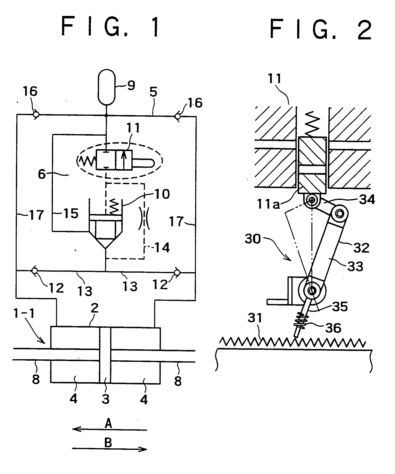
[0057] In thus-structured hydraulic damper 1, the first embodiment employs a mechanical drive means 30, as shown in FIG. 2, to allow the damping coefficient of the hydraulic damper 1 to be switched in two stages, that is, between the maximum value Cmax and the minimum value Cmin only with the hydraulic damper 1 that works in response to an external force.

[0058] The mechanical drive means 30 is composed of, for instance, a straight gear (rack) 31 fixed to a piston rod 8 and a crank mechanism 32 that works with the straight gear 31 to on-off control the on-off control operation valve 11. The crank mechanism 32 is structured so that a base part of a first link 33 is fixed to a cylinder side through a pin or the like to make the crank mechanism swing-able in a direction of movement of the piston, and a tip end of a second link 34 is connected to a valve body 11a of a spool or the like of the on-off control operation valve 11 through a pin or the like.

[0059] In addition, the first link ...

second embodiment

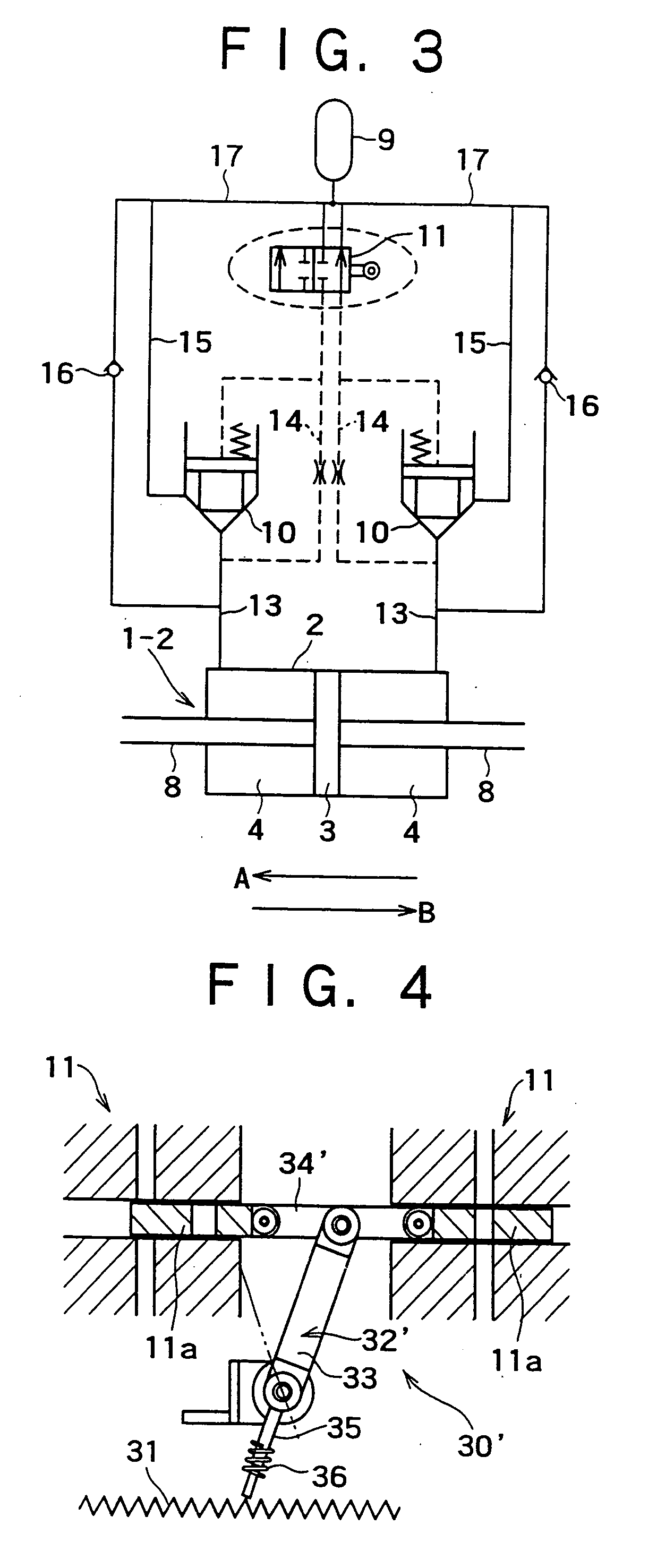
[0081] In the case of the above second embodiment, it is also noted that the mere use of the on-off control operation valve 11 is enough to perform switching of the damping coefficient without using the flow regulating valve 10, when the flow rate is not so high.

[0082] [III] Hydraulic Type of Damping Coefficient Switching-Type Hydraulic Damper (of Single Valve and Two Drive Part Type) 1-3

[0083] As shown in FIG. 5, in place of the mechanical drive means 30 of FIG. 1, a hydraulic drive means 40 is incorporated in the hydraulic circuit of FIG. 1 to perform switching of the damping coefficient with a change of hydraulic pressure.

[0084] The hydraulic drive means 40 is composed of a buffer 42 connected to each of inflow passages 17, 17 of the hydraulic chambers 4,4 through restrictions respectively and being used for storing pressure oil, and a selector valve (poppet valve) 43 connected to the buffer 42 and being used to on-off control the on-off control operation valve 11.

[0085] The s...

third embodiment

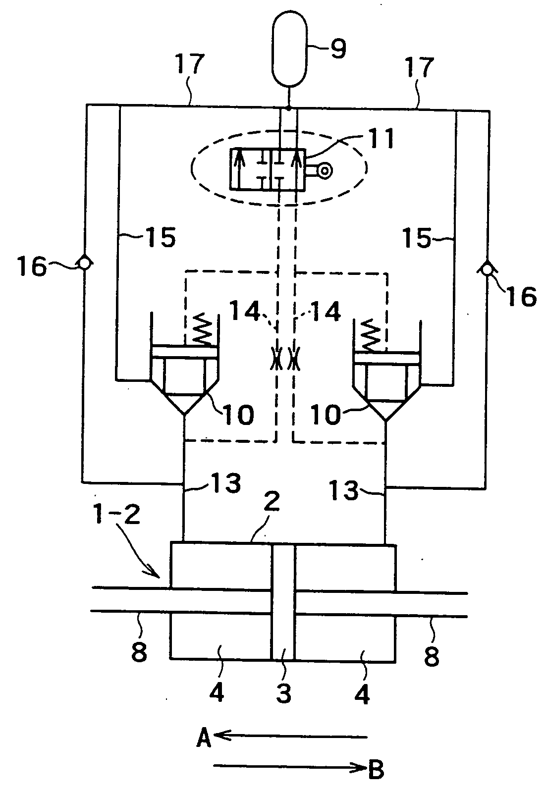
[0092] Although there are provided two on-off control operation valves 11, it is noted that the use of the single on-off control operation valve will do. In the case of the above third embodiment, it is also noted that the mere use of the on-off control operation valve 11 is enough to perform switching of the damping coefficient without using the flow regulating valve 10, when the flow rate is not so high.

[0093] [IV] Hydraulic-Type Damping Coefficient Switching-Type Hydraulic Damper (of Two Valve and Two Drive Part Type) 1-4

[0094] As shown in FIG. 6, this embodiment is that employing two flow regulating valves 10 arranged as right- and left-side flow regulating valves in the hydraulic circuit of FIG. 5. This embodiment is similar in other constitution to that of FIG. 5.

[0095] The hydraulic type of damping coefficient switching-type hydraulic damper 1-4 having the above structure operates as follows, like that of FIG. 5, except that the hydraulic damper 1-4 employs two flow regulat...


PUM


Abstract

There is disclosed a damping coefficient switching-type hydraulic damper that may automatically switch a damping coefficient without needing supply of energy from the outside at all, and also may always surely exert an energy absorption capacity greater than that of a typical hydraulic damper. While a piston (3) is moving in a direction A, a mechanical drive means (30) composed of a straight gear (31) and a crank mechanism (31) allows an on-off control operation valve (11), that is, a flow regulating valve (10) to be placed in a closed state, and a damping coefficient is switched to a maximum value Cmax. When a movement of the piston (3) is turned in a direction B at a left-side maximum point of amplitude, the mechanical drive means (30) works to once open the flow regulating valve (10) to perform elimination of a load, so that the damping coefficient is switched to a minimum value (Cmin). When the piston (3) further moves in the direction B, the mechanical drive means (30) works to close the flow regulating valve (10) again, and the damping coefficient is returned to the maximum value (Cmax). Similar working to the above is also applied to a right-side maximum point of amplitude, and seismic response control is attained with repetition of the above operations.

Description

TECHNICAL FIELD [0001] This invention relates to a hydraulic damper useful in reducing shaking of a structure (such as buildings, bridges and roofs) in response to vibrations and / or external forces such as earthquake and wind. BACKGROUND ART [0002] As one of damper-type seismic response control devices useful in reducing shaking of a structure, there is a variable damping device (as disclosed in Japanese Patent Laid-open No. 11-336366, for instance) or the like structured so that a valve opening of an on-off control valve is controllable in two stages so as to be switched between a full open position and a full closed position. [0003] The above hydraulic damper has a basic structure as shown in FIG. 11, and, specifically, includes a cylinder 2, a double rod-type piston 3 movable in a reciprocating manner within the cylinder 2, hydraulic chambers 4, 4 provided at the opposite sides of the piston 3, an on-off control valve 6 provided in a passage 5 for connecting both the hydraulic ch...

Claims


Application Information

Patent Timeline
IPC IPC(8): B60G17/015B60G17/08E04H9/02F16F9/48
CPCB60G17/0152F16F15/027B60G2202/154B60G2202/24B60G2202/413B60G2202/414B60G2202/415B60G2500/114B60G2500/2014E04H9/02E04H9/028E04H2009/026F16F9/20F16F9/46F16F9/48F16F9/512B60G17/08E04H9/0235E04H9/0237
Inventor MATSUNAGA, YOSHINORIKURINO, HARUHIKO
Owner KAJIMA CORP
Why Eureka
Try Eureka