Plasma processing device and plasma processing method
a plasma treatment and plasma technology, applied in the direction of plasma technique, chemical vapor deposition coating, coating, etc., can solve the problems of increasing the temperature of the plasma ejected from the discharge space, the inability to use plasma treatment methods for films with poor heat resistance, and the high cost of high-frequency power sources and impedance matching devices. , to achieve the effect of reducing the plasma temperature, ensuring the effect of plasma treatment capability and stable discharg
- Summary
- Abstract
- Description
- Claims
- Application Information
AI Technical Summary
Benefits of technology
Problems solved by technology
Method used
Image
Examples
examples
[0162] The present invention is specifically explained below according to Examples.
examples 1-5
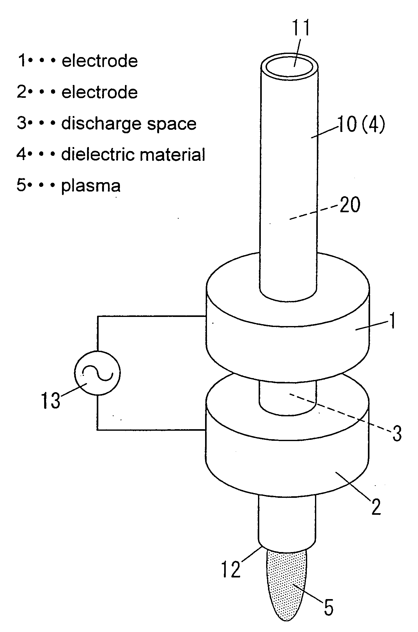
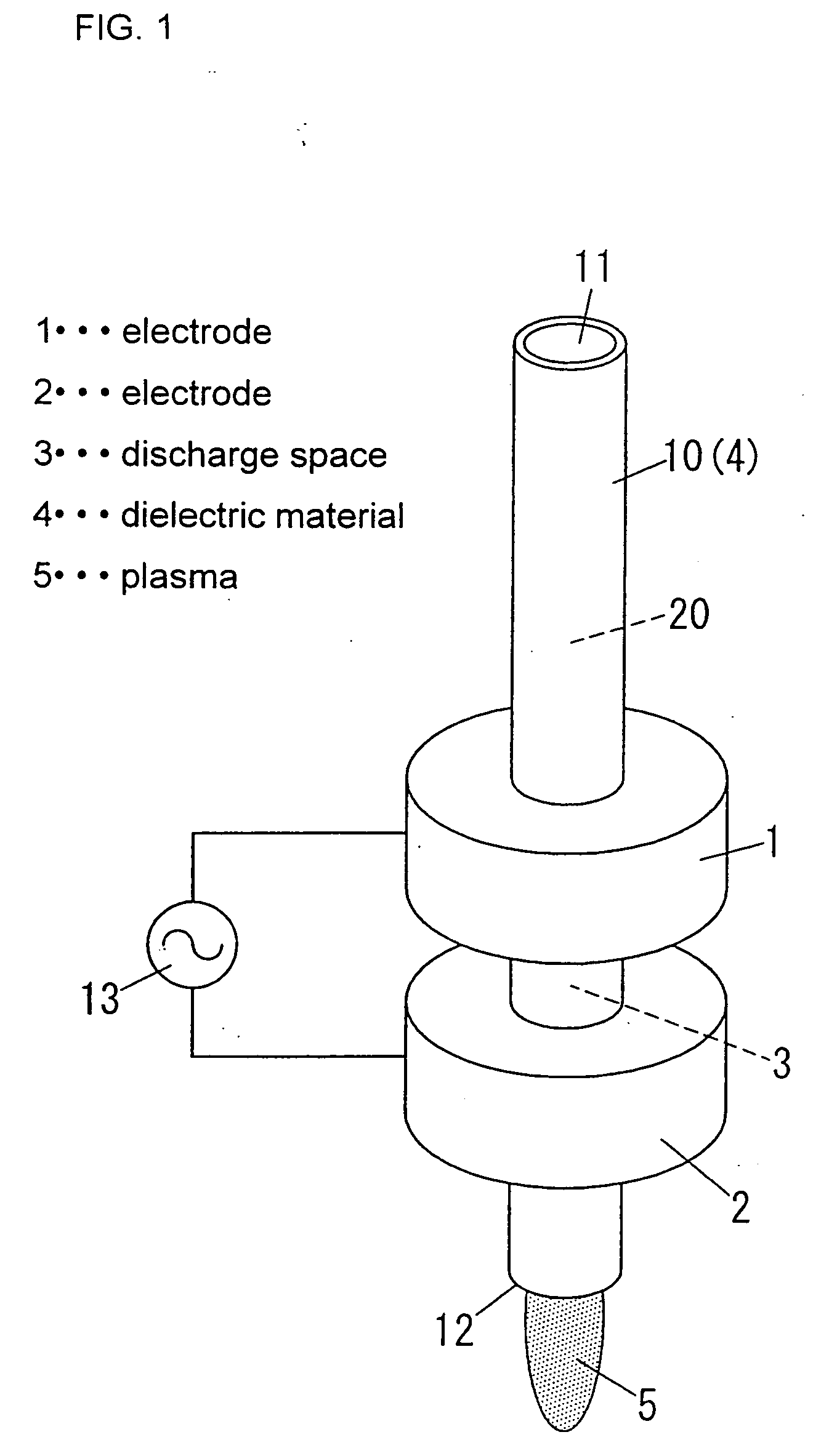
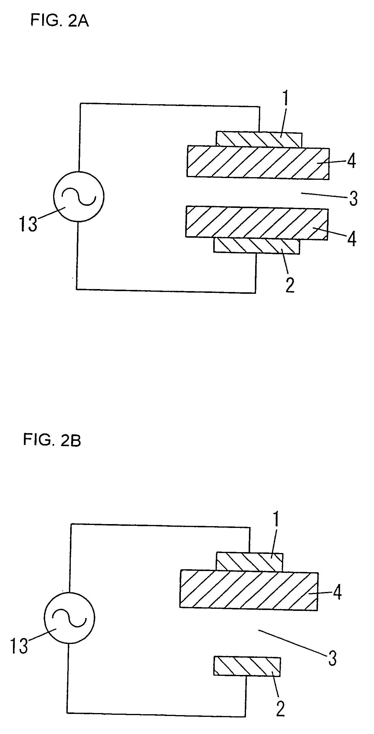
[0163] A plasma treatment apparatus for spot treatment shown in FIG. 16 was used. A reaction vessel 10 of this plasma treatment apparatus is of a quartz pipe having the inner diameter of 3 mm and the outer diameter of 5 mm, which is provided with a hollow flange portion 6 (retention area 15) having the outer diameter of 50 mm. Electrodes 1, 2 and the flange portion 6 are arranged so as to have the cross-sectional structure shown-in FIG. 17.
[0164] A plasma generation gas was supplied into a gas flow channel 20 from an gas inlet 11 of the reaction vessel 10, and a plasma was generated by a voltage supplied from a power source 13 connected to the electrode 1 of the upstream side and the electrode 2 of the downstream side. The plasma 5 was ejected from an outlet 12. By exposing an object placed at the downstream side of the outlet 12 to the plasma, the plasma treatment was carried out. As the plasma generation gas, a mixture of argon and oxygen was used. Other conditions of generating ...
examples 6 to 10
[0192] A plasma treatment apparatus for wide treatment shown in FIG. 22 was used. A reaction vessel 10 of this apparatus is made of quartz glass, and has the inner size of 1 mm×30 mm, which has a slit-like outlet 12 and a hollow flange portion 6 (retention area 15). Other configurations are substantially the same as Examples 1 to 5. Plasma was generated under the plasma generating conditions shown in Table 3. As in the case of Examples 1 to 5, the same evaluations were carried out.
PUM
| Property | Measurement | Unit |
|---|---|---|
| repetition frequency | aaaaa | aaaaa |
| time | aaaaa | aaaaa |
| falling time | aaaaa | aaaaa |
Abstract
Description
Claims
Application Information
 - R&D
- Intellectual Property
- Life Sciences
- Materials
- Tech Scout
- Unparalleled Data Quality
- Higher Quality Content
- 60% Fewer Hallucinations
Browse by: Latest US Patents, China's latest patents, Technical Efficacy Thesaurus, Application Domain, Technology Topic, Popular Technical Reports.
© 2025 PatSnap. All rights reserved.Legal|Privacy policy|Modern Slavery Act Transparency Statement|Sitemap|About US| Contact US: help@patsnap.com


