Method and device for estimating remaining capacity of secondary cell battery pack system and electric vehicle

a secondary cell battery pack and remaining capacity technology, applied in secondary cell servicing/maintenance, batteries, instruments, etc., can solve the problems of secondary battery not being able to supply electric power, secondary battery cannot find a suitable charging efficiency, and cannot calculate self-discharge amount during that time, so as to achieve the effect of reducing the deviation of the soc estimated value and the soc true value, high accuracy and reducing the charge efficiency

Active Publication Date: 2005-01-27
PANASONIC EV ENERGY CO LTD
View PDF24 Cites 38 Cited by
  • Summary
  • Abstract
  • Description
  • Claims
  • Application Information

AI Technical Summary

Benefits of technology

[0042] According to the above configuration, in the case where, as a microcomputer system, for example, a battery pack system with a battery ECU mounted thereon is mounted on, for example, an HEV, etc., an SOC can be controlled exactly based on the SOC estimated with high accuracy. More specifically, in the case where the SOC estimated by computation (SOC estimated value) is determined to be higher than a true SOC (SOC true value), the charging efficiency is reduced by a correction amount of the current accumulation coefficient. As a result, the SOC estimated value is decreased at subsequent accumulation, compared with the previous accumulation, so that the SOC estimated value is approximated to the SOC true value. On the other hand, in the case where the SOC estimated value is determined to be lower than the SOC true value, the charging efficiency is added by a correction amount of the current accumulation coefficient. As a result, the SOC estimated value is increased at subsequent accumulation, compared with the previous accumulation, so that the SOC estimated value also is approximated to the SOC true value. Thus, by continuing this control, the SOC estimated value and the SOC true value are managed so as to be always matched with each other, and the deviation of the SOC estimated value with respect to the SOC true value is decreased. This can remarkably enhance the accuracy of energy management of an entire system.

Problems solved by technology

However, the above-mentioned two kinds of conventional SOC estimation methods have the following problems.
Therefore, it is difficult to find a charging efficiency suitable for these various kinds of conditions.
Furthermore, in the case where a battery is being left, a self-discharge amount during that time cannot be calculated.
However, in the case where a secondary battery is mounted on an HEV, when complete discharging is performed, the secondary battery cannot supply electric power, which becomes a burden on an engine.
Thus, in the case of the application to an HEV, it is impossible to perform complete charging / discharging during driving of a vehicle so as to initialize an SOC.
Furthermore, to periodically perform complete charging / discharging of a secondary battery mounted on an HEV is inconvenient for a user, and also becomes a burden on the user.
Because of this, the difference in voltage turns to be an estimation error of an SOC.
Furthermore, a decrease in voltage due to a memory effect and leaving of a battery, battery degradation, and the like also cause an estimation error of an SOC.
Furthermore, according to the above-mentioned conventional method for estimating a polarization voltage, when a polarization voltage is obtained by a polarization resistance, a reaction resistance due to the reaction between an active material of a battery and an interface of an electrolyte solution and a diffusion resistance due to the reaction in active materials, between active materials, and in an electrolyte solution, included in a polarization resistance, cannot be estimated sufficiently.
Therefore, the accuracy of an estimated polarization voltage is unsatisfactory.
Accordingly, it is not practical to use a no-load voltage in the above method (2) for correction, in order to obtain a battery electromotive force for estimating an SOC.

Method used


Image

  • Method and device for estimating remaining capacity of secondary cell battery pack system and electric vehicle
  • Method and device for estimating remaining capacity of secondary cell battery pack system and electric vehicle
  • Method and device for estimating remaining capacity of secondary cell battery pack system and electric vehicle

Examples


embodiment 1

[0084] (Embodiment 1)

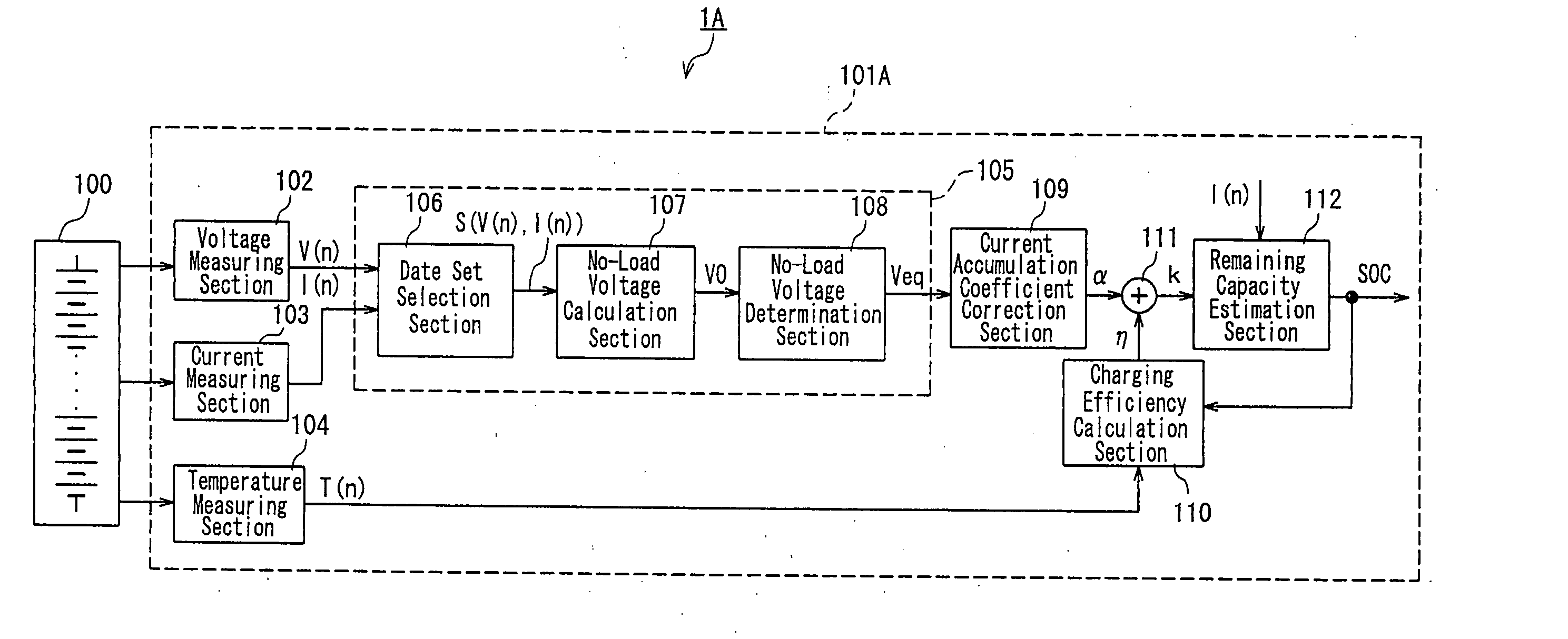
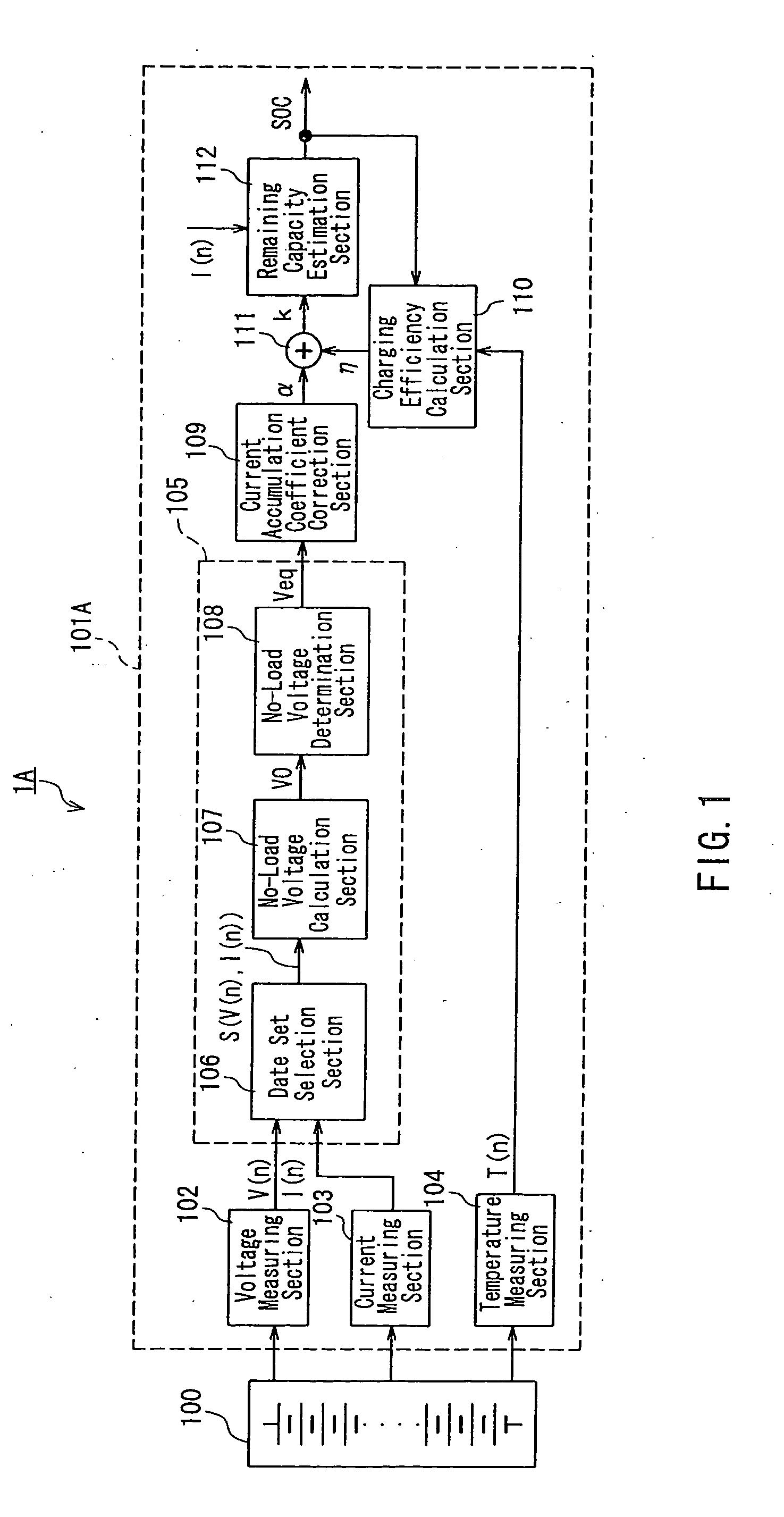
[0085]FIG. 1 is a block diagram showing an exemplary configuration of a battery pack system 1A according to Embodiment 1 of the present invention. In FIG. 1, the battery pack system 1A is composed of a battery pack 100 and a battery ECU 101A including an apparatus for estimating a remaining capacity according to the present invention as a part of a microcomputer system.

[0086] The battery pack 100 has a configuration in which a plurality of battery modules (cells), each having a plurality of cells (e.g., nickel-metal hydride batteries) electrically connected in series, are electrically connected in series, so as to obtain a predetermined output, generally when mounted on an HEV, etc.

[0087] In the battery ECU 101A, reference numeral 102 denotes a voltage measuring section for measuring a terminal voltage of the secondary battery 100 detected by a voltage sensor (not shown) at a predetermined sampling period as voltage data V(n), 103 denotes a current measuring s...

embodiment 2

[0099] Embodiment 2

[0100]FIG. 4 is a block diagram showing an exemplary configuration of a battery pack system according to Embodiment 2 of the present invention. In FIG. 4, the same components as those shown in FIG. 1 representing the configuration of Embodiment 1 are denoted with the same reference numerals as those therein, and the description thereof will be omitted here.

[0101] In the present embodiment, an estimated electromotive force calculation section 113 and a subtractor 114 are added to Embodiment 1 to configure a battery ECU 101B.

[0102] The estimated electromotive force calculation section 113 obtains an estimated electromotive force Ves from a currently estimated SOC. The subtractor 114 subtracts the estimated electromotive force Ves, which is calculated in the estimated electromotive force calculation section 113, from the electromotive force Veq, which is calculated in the electromotive force calculation section 105, and outputs an electromotive force deviation Vd t...

embodiment 3

[0108] Embodiment 3

[0109]FIG. 6 is a block diagram showing an exemplary configuration of a battery pack system 1C according to Embodiment 3 of the present invention. In FIG. 6, the same components as those shown in FIG. 4 representing the configuration of Embodiment 2 are denoted with the same reference numerals as those therein, and the description thereof will be omitted here.

[0110] In the present embodiment, a varied capacity calculation section 115, a first computation section 116, a polarization voltage calculation section 117, and a subtractor 118 are added to the electromotive force calculation section 105 of Embodiment 2 to obtain an electromotive force calculation section 105′, whereby a battery ECU 101C is configured.

[0111] The varied capacity calculation section 115 obtains a variation ΔQ of the accumulated capacity during a past predetermined period (e.g., one minute) from the current data I(n).

[0112] The first computation section 116 functions as a low-pass filter (L...


PUM

PropertyMeasurementUnit
charging/discharging currentsaaaaaaaaaa
terminal voltageaaaaaaaaaa
electromotive forceaaaaaaaaaa

Abstract

There is provided a battery pack system with estimation accuracy of a remaining capacity of a secondary batter enhanced. A current accumulation coefficient correction section 109 calculates a correction amount α with respect to a current accumulation coefficient k in accordance with a battery electromotive force Veq from an electromotive force calculation section 105. A remaining capacity calculation section 112 estimates a remaining capacity SOC by current accumulation, based on the current accumulation coefficient k calculated from a correction amount α, and a charging efficiency η based on a currently estimated remaining capacity calculated by a charging efficiency calculation section 110.

Description

TECHNICAL FIELD [0001] The present invention relates to a method for estimating a remaining capacity (SOC: State of Charge) of a secondary battery such as a nickel-metal hydride (Ni—MH) battery to be mounted as a power source for a motor and a driving source for various loads, in motor-driven vehicles such as a pure electric vehicle (PEV), a hybrid electric vehicle (HEV), a hybrid vehicle with a fuel battery and a battery, or the like. BACKGROUND ART [0002] Conventionally, in an HEV, when an output from an engine is large with respect to motive power required for driving, an electric generator is driven with surplus motive power to charge a secondary battery. On the other hand, when an output from an engine is small, a motor is driven with the electric power from a secondary battery to output supplementary motive power. In this case, a secondary battery is discharged. When a secondary battery is mounted on an HEV or the like, it is necessary to maintain an appropriate operation stat...

Claims


Application Information

Patent Timeline
Patent Type & Authority Applications(United States)
IPC IPC(8): B60L11/18B60L50/10G01R31/36H01M10/48
CPCB60L3/0046Y02T10/70B60L11/1861B60L11/1868B60L2240/545B60L2240/547B60L2240/549B60L2260/44G01R31/3606H01M10/48Y02T10/7005Y02T10/7044Y02T10/7066Y02T10/7077B60L11/02G01R31/382B60L50/10B60L58/20B60L58/18Y02T10/7072Y02E60/10G01R31/3832H02J7/0048H01M10/425H01M50/20H01M2220/20
Inventor MURAKAMI, YUSAITAKADA, MASAHIROEGOSHI, TERUYOSHIYAMABE, NORITO
Owner PANASONIC EV ENERGY CO LTD
Why Eureka
Try Eureka