Loop filter for class D amplifiers

a loop filter and amplifier technology, applied in the field of audio amplifiers, can solve the problems of deviation from theoretical behavior, non-idealities in the observed electrical performance of conventional natural sampling pwm modulator, and theoretically less efficient ab amplifiers, so as to reduce aliasing error and not decrease the stability of the loop filter

Active Publication Date: 2005-01-27
TEXAS INSTR INC
View PDF3 Cites 50 Cited by
  • Summary
  • Abstract
  • Description
  • Claims
  • Application Information

AI Technical Summary

Benefits of technology

It is a further object of this invention to provide such a class D amplifier in which the stability of the loop filter is not decreased while reducing the aliasing error.

Problems solved by technology

While the non-zero bias current renders class AB amplifiers theoretically less efficient than class B amplifiers, class AB amplifiers avoid the crossover distortion of class B amplifiers.
In practice, however, non-idealities in the observed electrical performance of conventional natural sampling PWM modulator 1 indicate deviations from theoretical behavior, especially from the downstream switching power stage that is controlled by PWM output signal p(t).
For example, noise and distortion arises from switching delays in the downstream power stage that vary non-linearly with load current.
In the modulator itself, errors such as amplitude distortion and noise in the triangle wave signal will be evident as distortion and noise in the PWM output signal p(t).
Comparator 5 may itself also contribute to distortion and noise.
In addition, noise, ripple, and variations in the power supply voltage biasing the downstream switching stage will also introduce errors in the ultimate output.
Another non-ideal factor that affects the fidelity of class D amplifiers is ripple in the output signal p(t).
Another concern faced by the designer of a PWM loop for audio amplification is the error due to aliasing in the feedback loop.
This aliasing is, of course, undesirable for audio fidelity.
These high components are referred to as the ripple signal, which will produce an aliasing error when sampled by the comparator.
However, it has been observed that the error function of the loop will be effectively set by the second-order integrator, and the error will scale with K2.
The error suppression in the base-band also scales with K2, in which case the closed loop error will effectively be constant, such that increasing the second-order feedback by scaling K2 will be ineffective in decreasing distortion.

Method used


Image

  • Loop filter for class D amplifiers
  • Loop filter for class D amplifiers
  • Loop filter for class D amplifiers

Examples


Embodiment Construction

The present invention will be described in connection with its preferred embodiment, namely as implemented into an audio amplifier, because it is contemplated that this invention is especially beneficial in such an application. However, it is also contemplated that the benefits of this invention can also be attained in other applications, such as switching power supplies, and motor control drivers such as used in disk drives. Accordingly, it is to be understood that the following description is provided by way of example only, and is not intended to limit the true scope of this invention as claimed.

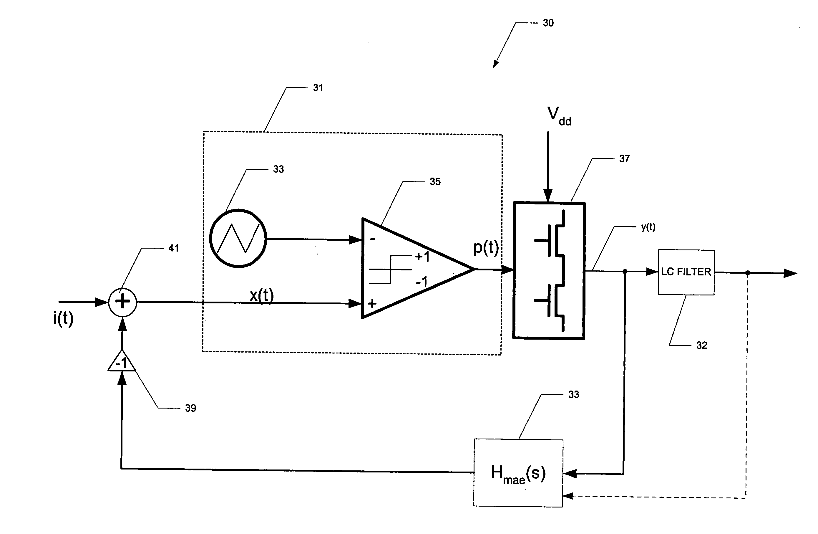
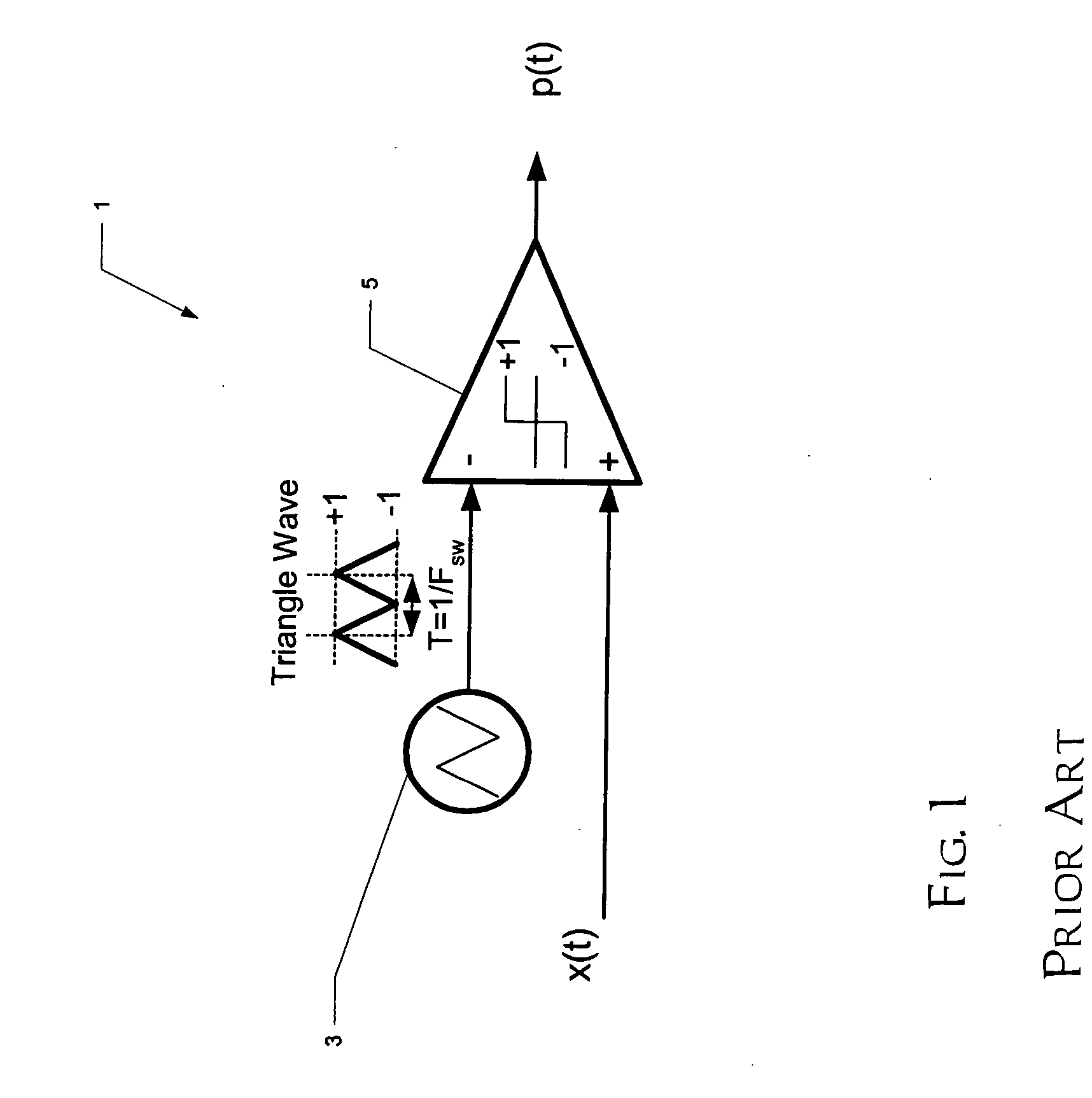
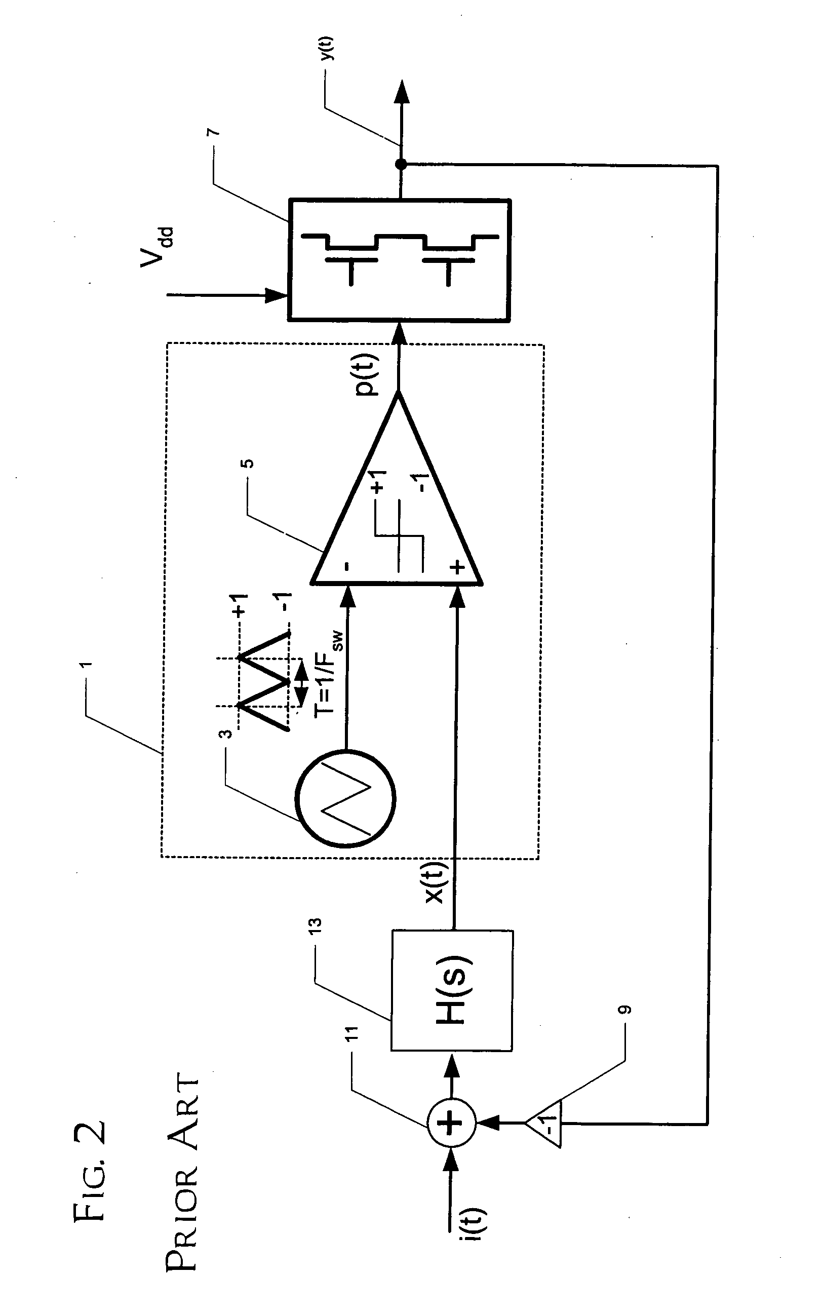
The present invention is based on certain observations regarding the operation of loop filters in class D amplifiers, such as the conventional feedback-controlled class D amplifier of FIG. 2. As mentioned above, high frequency components of the output signal p(t) from conventional PWM modulators will feed back to the input of the comparator of the PWM modulator itself. These high frequ...


PUM


Abstract

A class-D amplifier circuit (30; 30′) providing improved open-loop error for base-band frequencies, such as the audio band, is disclosed. The amplifier circuit (30; 30′) includes a comparator (35) for generating a pulse-width-modulated output signal that is applied to an output power stage (37). An LC filter (32) is at the output of the power stage (37). The amplifier circuit (30; 30′) includes a loop filter having multiple feedback loop paths, with at least one feedback loop path coupled to the output of the power stage (37), and optionally, at least one feedback loop path coupled to the output of the LC filter (32). The transfer function (Hmae(s)) of the loop filter has a real part that has a much steeper slope (on the order of 80 dB / decade) at frequencies above the pulse-width-modulation switching frequency than the slope of its magnitude characteristic at frequencies below this switching frequency.

Description

STATEMENT REGARDING FEDERALLY SPONSORED RESEARCH OR DEVELOPMENT Not applicable. BACKGROUND OF THE INVENTION This invention is in the field of audio amplifiers, and is more specifically directed to pulse-width modulated class D audio power amplifiers. As is fundamental in the art, electronic amplifier circuits are often classified in various “classes”. For example, the output drive transistors of class A amplifier circuits conduct DC current even with no audio signal, and the entire output voltage swing is of a single polarity. A class B amplifier, on the other hand, typically includes complementary output drive transistors, driving an output voltage swing including both positive and negative polarity excursions. Class B amplifiers are necessarily more efficient, because both complementary output drive transistors are never on at the same time. Class AB amplifiers maintain a small bias current through complementary output drive transistors, so that the output voltage swing is cent...

Claims


Application Information

Patent Timeline
Patent Type & Authority Applications(United States)
IPC IPC(8): H03F3/217
CPCH03F3/217H03F2200/78H03F2200/331H03F3/2171
Inventor RISBO, LARSNEESGAARD, CLAUS N.
Owner TEXAS INSTR INC
Why Eureka
Try Eureka