Method and apparatus for forming millimeter wave phased array antenna

a phased array and millimeter wave technology, applied in the direction of individual energised antenna arrays, resonant antennas, structural forms of radiating elements, etc., can solve the problems of increasing system complexity and cost, reducing the spacing between radiating elements, and becoming difficult to physically configure control electronics and interconnects within the increasingly tight element spacing, etc., to achieve simple structure, reduce system efficiency, and tight element spacing

Active Publication Date: 2005-01-27
THE BOEING CO
View PDF13 Cites 26 Cited by
  • Summary
  • Abstract
  • Description
  • Claims
  • Application Information

AI Technical Summary

Benefits of technology

[0011] In one preferred form the first waveguide structure comprises a rectangular air waveguide structure. This structure feeds EM wave input energy from an input thereof into a plurality of outputs and divides the EM wave energy among the plurality of outputs. These outputs feed the second waveguide structure which, in one preferred form, includes a plurality of dielectrically-filled circular waveguides. The second waveguide structure channels the EM wave energy to a corresponding plurality of inputs of the stripline waveguide structure where this EM wave energy is further successively divided before being applied to each of the radiating elements of the plurality of antenna modules of the antenna system. The use of the corporate stripline waveguide structure allows extremely tight element spacing to be achieved with only a very small reduction in efficiency of the system. The use of the corporate stripline waveguide structure fur

Problems solved by technology

As the antenna operating frequency increases, the required spacing between radiating elements decreases and it becomes difficult to physically configure the control electronics and interconnects within the increasingly tight element spacing.
Relaxing the tight element spacing will degrade the beam scanning performance, but adequately providing multiple interconnects requires stringent manufacturing and assembly tolerances which increase system complexity and cost.
Consequently, the performance and cost of the phased array antenna depends primarily on module packaging and distribution network interconnects.
Multiple beam applications further complicate this problem by requiring more electronic components and interconnects within the same antenna volume.
Series distribution networks are often limited in instantaneous bandwidth because of the various delays which the EM wave signal experiences during the distribution.
However, parallel distribution increases in difficulty with a large number of

Method used


Image

  • Method and apparatus for forming millimeter wave phased array antenna
  • Method and apparatus for forming millimeter wave phased array antenna
  • Method and apparatus for forming millimeter wave phased array antenna

Examples


Embodiment Construction

[0026] The following description of the preferred embodiment(s) is merely exemplary in nature and is in no way intended to limit the invention, its application, or uses.

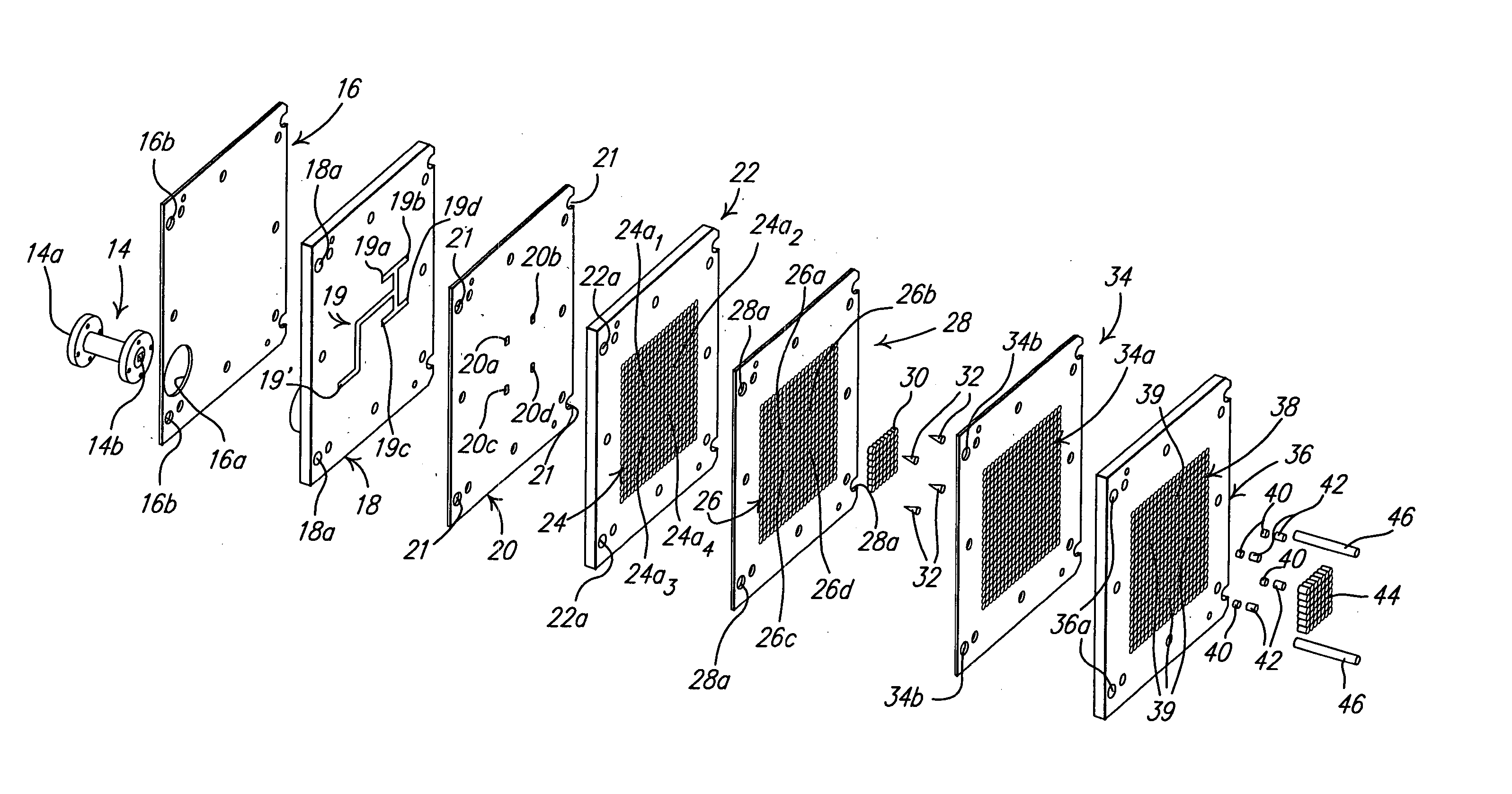
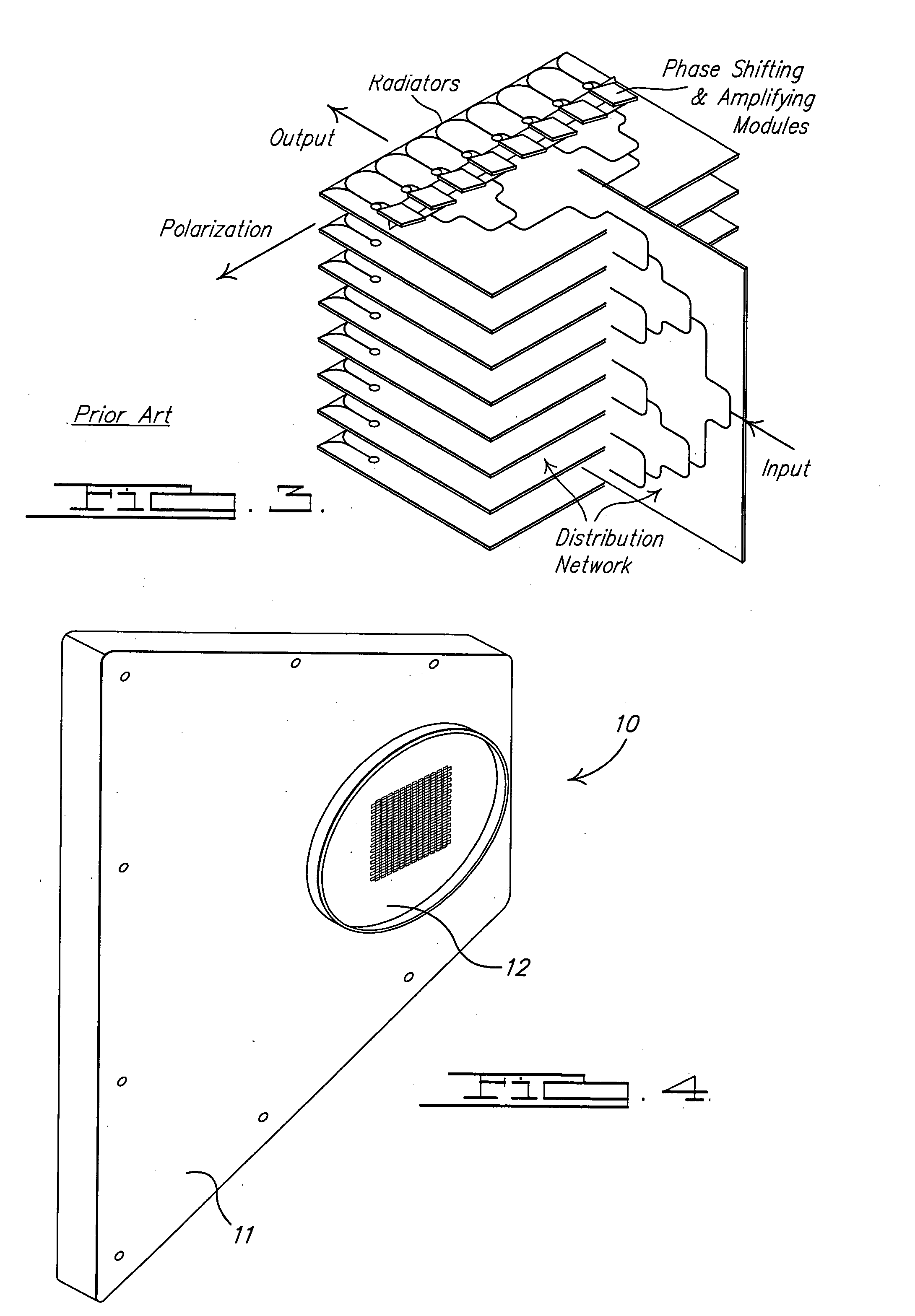
[0027] Referring to FIG. 4, an antenna system 10 in accordance with a preferred embodiment and method of the present invention is shown. The antenna system 10 forms an antenna able to operate at millimeter wavelengths, and more particularly at 44 GHz (Q-band) and in accordance with the MILSTAR protocol without requiring advance knowledge of the next beam hopping frequency being employed in a MILSTAR application. The antenna system 10 forms a dual beam system having a plurality of 524 independent antenna modules very closely spaced relative to one another to enable operation at millimeter wave frequencies, and more preferably at about 44 GHz, without suffering significant beam degradation and performance at scan angles up to (or exceeding) 60 degrees. The antenna system generally includes a chassis 11 within which is...


PUM


Abstract

A phased array antenna system having a corporate waveguide distribution network stripline printed circuit board. The stripline printed circuit board receives electromagnetic (EM) wave energy from a 1×4 waveguide distribution network input plate and distributes the EM wave energy to 524 radiating elements. The stripline circuit board enables extremely tight spacing of independent antenna radiating elements that would not be possible with a rectangular air filled waveguide. The antenna system enables operation at millimeter wave frequencies, and particularly at 44 GHz, and without requiring the use of a plurality of look-up tables for various phase and amplitude delays, that would otherwise be required with a rectangular, air-filled waveguide distribution structure. The antenna system can be used at millimeter wave frequencies, and in connection with the MILSTAR communications protocol, without the requirement of knowing, in advance, the next beam hopping frequency employed by the MILSTAR protocol.

Description

FIELD OF THE INVENTION [0001] The present invention relates to antennas, and more particularly to an electronically scanned, dual beam phased array antenna capable of operating at millimeter wavelengths and incorporating a corporate stripline waveguide structure. BACKGROUND OF THE INVENTION [0002] A phased array antenna is composed of multiple radiating antenna elements, individual element control circuits, a signal distribution network, signal control circuitry, a power supply, and a mechanical support structure. The total gain, effective isotropic radiated power and scanning and side lobe requirements of the antenna are directly related to the number of elements in the antenna aperture, the element spacing, and the performance of the elements and element electronics. In many applications, thousands of independent element / control circuits are required to achieve a desired antenna performance. A typical phased array antenna includes independent electronic packages for the radiating ...

Claims


Application Information

Patent Timeline
IPC IPC(8): H01Q21/06
CPCH01Q21/065
Inventor NAVARRO, JULIO A.O'CONNELL, JOHN B.BOSTWICK, RICHARD N.
Owner THE BOEING CO
Why Eureka
Try Eureka