
Apparatus for simultaneous OTDM demultiplexing, electrical clock recovery and optical clock generation, and optical clock recovery

a technology of optical clock and multi-core processor, applied in the direction of optics, instruments, electrical apparatus, etc., can solve the problems of ambiguity and crosstalk, high cost, and use of circulator, so as to reduce the number of high-speed components of the otdm network node, increase reliability, and reduce costs

Inactive Publication Date: 2005-01-27
KDDI R&D LAB INC +1
View PDF9 Cites 14 Cited by
  • Summary
  • Abstract
  • Description
  • Claims
  • Application Information

AI Technical Summary

Benefits of technology

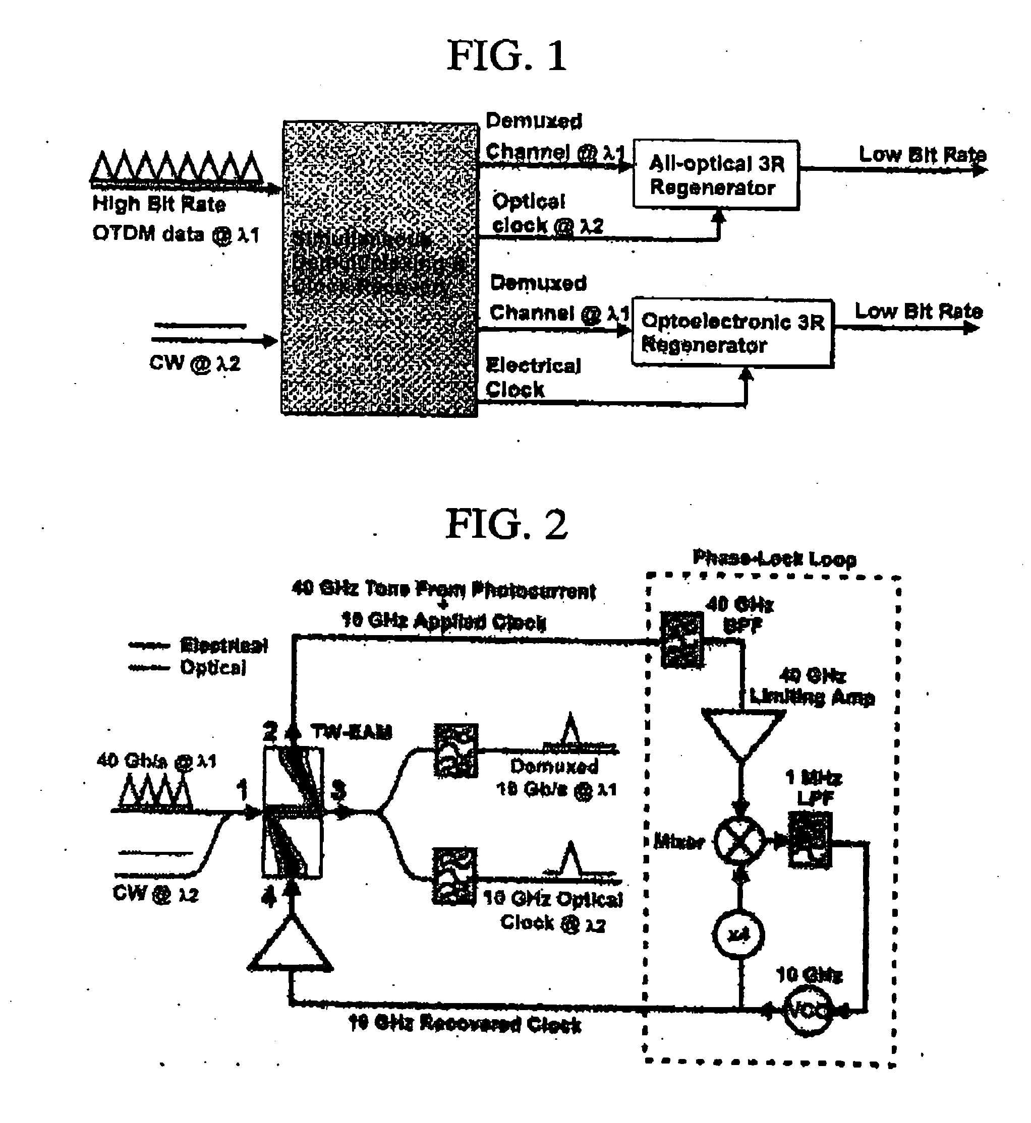
[0014] The invention is a new compact scheme of simultaneous demultiplexing, electrical clock recovery and optical clock generation for OTDM signals. The invention described herein presents a new concept of utilizing independent electrical frequency division to fulfill simultaneous demultiplexing, electrical clock recovery and optical clock generation in the same one traveling wave electroabsorption modulator (TW-EAM) without the ambiguity and the crosstalk problems. The photocurrent of the TW-EAM is employed to detect the data information, and then different independent electrical frequency components are simultaneously used for recovering the electrical clock through a phase-lock loop (PLL), demultiplexing and optical clock generation, respectively. Accordingly, the TW-EAM works simultaneously as a photodetector, a demultiplexer, and an optical pulse generator. The invention exploits the devices multiple functionalities that allow the number of high-speed components within an OTDM network node to be reduced, therefore increasing reliability, whilst also substantially reducing costs.
[0019] The invention exploits the low-cost implementation of optical clock recovery by using a TW-EAM with two electrical ports and two optical ports wherein the TW-EAM can work as a photodiode and pulse generator simultaneously. On one hand, the photocurrent of the TW-EAM detects the data information that is then employed for recovering the electrical clock through the PLL. On the other hand, the electrical recovery clock is used to modulate the TW-EAM and generate an optical clock at another wavelength. Accordingly, the TW-EAM works as a photodiode and a pulse generator simultaneously so that the number of the required components for optical clock recovery can be reduced, thereby substantially reducing the cost

Problems solved by technology

However, the possible problems of the ambiguity and the crosstalk could occur in the single one device that is employed for multiple different purposes at the same time.
Regarding pulsed light other than a traveling wave, a circulator is used, but is expensive.

Method used


Image

  • Apparatus for simultaneous OTDM demultiplexing, electrical clock recovery and optical clock generation, and optical clock recovery
  • Apparatus for simultaneous OTDM demultiplexing, electrical clock recovery and optical clock generation, and optical clock recovery
  • Apparatus for simultaneous OTDM demultiplexing, electrical clock recovery and optical clock generation, and optical clock recovery

Examples


Embodiment Construction

[0039] The invention presents a new scheme for simultaneously OTDM signal demultiplexing, electrical clock recovery and optical clock generation using single one TW-EAM in order to reduce the cost and complexity of the network node. Except that the TW-EAM works as a compact demultiplexing receiver, another possible application is to convert high bit rate OTDM data to low bit rate.

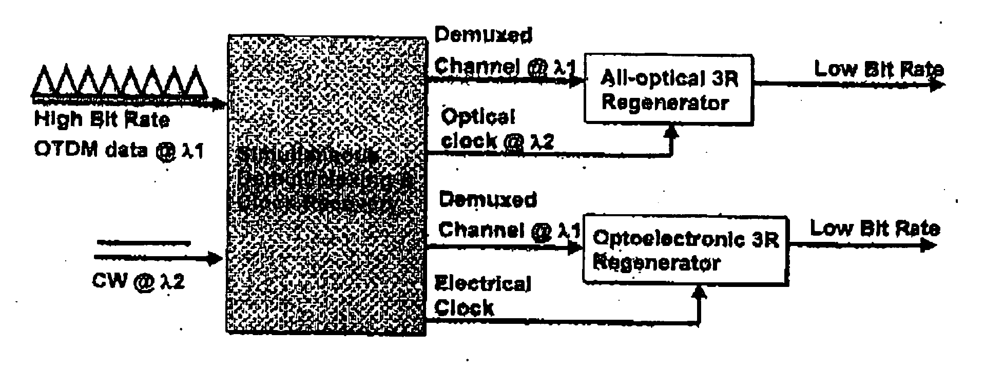
[0040]FIG. 1 is a schematic diagram that illustrates a general function of the invention. The ability to convert all channels of a high-speed OTDM data stream to a low-speed data stream with correct synchronization is significant at a network node for future processing such as from core network to access network. Thus, the relatively low-speed and low-cost equipments can be used for switching and detection purposes even when an ultra-high speed OTDM data stream enters the node. Depending on the types of the 3R regenerators (all-optical or optoelectric), either generated optical clock or recovered electrica...


PUM

PropertyMeasurementUnit
frequencyaaaaaaaaaa
frequencyaaaaaaaaaa
photocurrentaaaaaaaaaa

Abstract

An apparatus for simultaneous OTDM demultiplexing, electrical clock recovery and optical clock generation, and optical clock recovery using a traveling-wave electroabsorption modulator. The apparatus includes a TW-EAM and a PLL coupled thereto. The TW-EAM includes a first, a second, a third, and a fourth. The first port is used for an optical input and the third port is used for optical output. The second port is coupled to an input, and the fourth port is coupled to an output, of the PLL. When the first port receives optical input, the second port produces a photocurrent to be applied to the PLL, and the fourth port receives a recovered clock produced by the PLL, and the third port produces demultiplexed data and an optical clock. Using the same configuration, the apparatus produces a recovered optical clock signal.

Description

PRIORITY CLAIM [0001] Priority is claimed on provisional U.S. Patent Application Nos. 60 / 458,078, filed Mar. 26, 2003, and 60 / 459,667, filed Apr. 1, 2003,the content of which is incorporated herein by reference.COPY RIGHT RIGHTS [0002] A portion of the material in this patent document is subject to copyright protection under the copyright laws of the United States and of other countries. The owner of the copyright rights has no objection to the facsimile reproduction by anyone of the patent document or the patent disclosure, as it appears in the United States Patent and Trademark Office publicly available file or records, but otherwise reserves all copyright rights whatsoever. The copyright owner does not hereby waive any of its rights to have this patent document maintained in secrecy, including without limitation its rights pursuant to 37 C.F.R. § 1.14. BACKGROUND OF THE INVENTION [0003] 1. Field of the Invention [0004] The invention relates to an apparatus for simultaneous OTM de...

Claims


Application Information

Patent Timeline
Patent Type & Authority Applications(United States)
IPC IPC(8): G02F1/025H04B10/148H04J14/08
CPCH04J14/08H04B10/61
Inventor HU, ZHAOYANGNISHIMURA, KOHSUKECHOU, HSU-FENGBLUMENTHAL, DANIEL J.BOWERS, JOHN E.INOHARA, RYOUSAMI, MASASHI
Owner KDDI R&D LAB INC
Learn More