Braced microscope

a microscope and brace technology, applied in the field of brace microscopes, can solve the problems of difficult to relate images to the real structure of the sample being viewed, general cost increase, and inability to achieve substantial performance gains, so as to improve the resolution and speed of image acquisition, improve contrast, and facilitate interpretation and acceptance.

Inactive Publication Date: 2005-01-27
1192062 ALBERTA
View PDF7 Cites 45 Cited by
  • Summary
  • Abstract
  • Description
  • Claims
  • Application Information

AI Technical Summary

Benefits of technology

[0015] While the concept of darkfield imaging is not new and the use of video positive to negative inversion is known in the television broadcast special effects field, the present invention is the first application of these unrelated techniques to obtain high contrast images of samples such as living biological material. The present invention provides particular advantages as it

Problems solved by technology

While there have been notable attempts to extend the capabilities of the light microscope, to date such attempts have not achieved substantial gains in performance and have generally been obtained at significantly increased costs.
Phase and interference contrast techniques introduced artifacts, some of which were asymmetrical, which made the images difficult to relate to the real structure of the samples being viewed.
Darkfield and fluorescent techniques presented image information in a form that is most unfamiliar to visual capabilities, much in the same way that we are unable to extract information from a photographic or electronic “negative” image.
In general, the frame/field rate of the c

Method used


Image

  • Braced microscope
  • Braced microscope
  • Braced microscope

Examples


Embodiment Construction

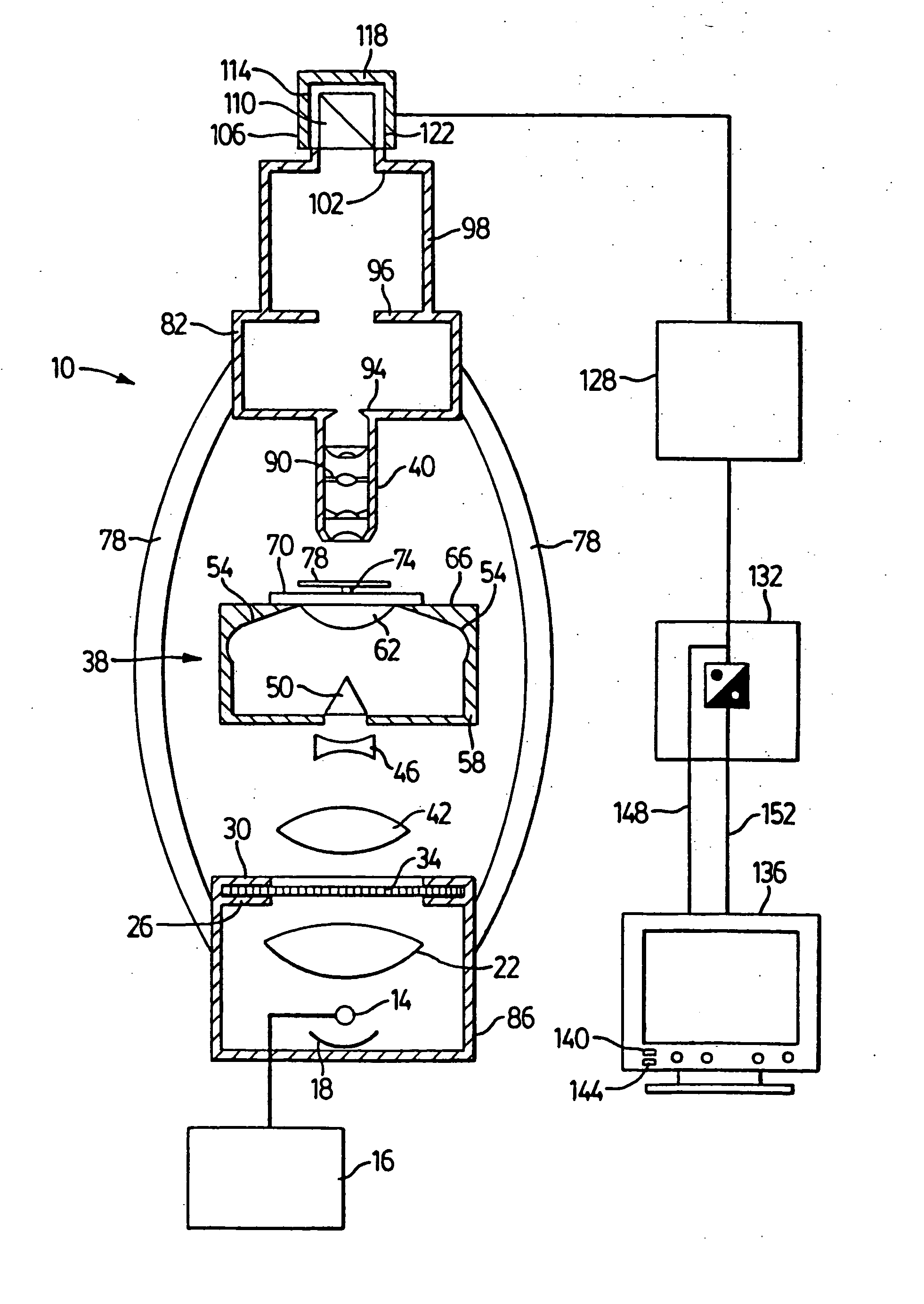
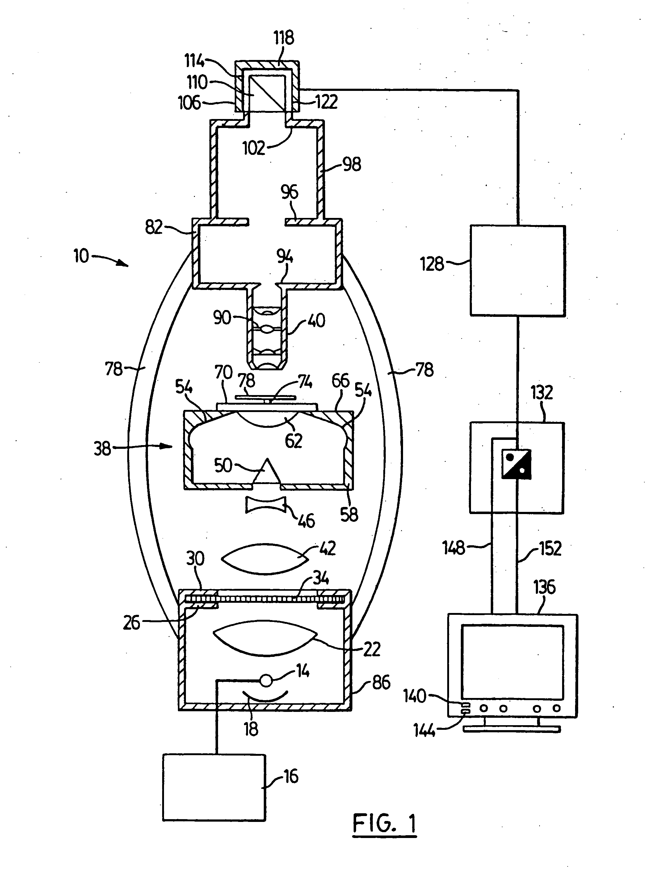
[0022] The present invention forms a darkfield image with a high numerical aperture (NA) optical system and electronically inverts the digitized darkfield image to produce a negative image of the darkfield image. The negative image is an apparent brightfield image, with very high contrast and resolution.

[0023] While it is possible to implement the method of the present invention using standard microscope illuminators, it is presently preferred that the light source employed with the present invention be considered on the basis of a “photon budget”, where the intended destination of each photon from the light source is mapped and accounted for in the design of the IDC microscope. In order to achieve this goal, in a presently preferred embodiment of the invention, the light source is selected and constructed as follows.

[0024] In conventional microscopes, tungsten, tungsten halogen, quartz halogen, or arc light sources are employed. These light sources are not well controlled in term...


PUM


Abstract

A novel microscope and method of obtaining images includes a combination of the conventional darkfield illuminations technique with electronic image inversion (converting a positive to a negative image) and other improvements to further enhance the contrast and resolution of the final image. The microscope and method are referred to herein as Inverted Darkfield Contrast (IDC) and are believed to be particularly suitable for viewing live cells in real time with no staining or preparation.

Description

[0001] This application is a continuation application of U.S. patent application Ser. No. 09 / 743,222, filed in the USPTO on Apr. 11, 2001, issued as U.S. Pat. No.______on______, which application is a 371 (national stage entry) of international patent application No. PCT / CA99 / 00626 filed on Jul. 12, 1999 and published under WO 00 / 03283 on Jan. 20, 2000, which application claims foreign priority from Canadian Patent Application No. 2,243,090 filed Jul. 10, 1998. All of these applications are incorporated herein by reference.FIELD OF THE INVENTION [0002] The present invention relates to microscopes and methods of obtaining images therewith. More particularly, the present invention relates to a method of obtaining images with Inverted Darkfield Contrast (IDC) microscopes and a novel IDC microscope. BACKGROUND OF THE INVENTION [0003] For many years light microscopes have been considered a mature technology. While there have been notable attempts to extend the capabilities of the light m...

Claims


Application Information

Patent Timeline
IPC IPC(8): G02B21/00G02B21/02G02B21/10G02B21/24G02B21/36G02B27/00
CPCG02B21/0088G02B21/02G02B21/10G02B27/0018G02B21/362G02B21/365G02B21/24
Inventor RICHARDSON, TIMOTHY M.
Owner 1192062 ALBERTA
Why Eureka
Try Eureka