Magnetically actuated fast MEMS mirrors and microscanners

a technology of magnets and mirrors, applied in the direction of optics, instruments, mountings, etc., can solve the problems of high power, high resolution and relatively large mems, and high and sometimes unreasonable driving voltages, and achieve high power and high resolution, high precision, and high scanning efficiency.

Inactive Publication Date: 2005-01-27
TERRAOP
View PDF4 Cites 68 Cited by
  • Summary
  • Abstract
  • Description
  • Claims
  • Application Information

AI Technical Summary

Benefits of technology

The invention discloses magnetically driven MEMS, one-directional (one angular degree of freedom or DOF) and bidirectional (two angular DOFs) micro-scanners, designed for the purpose of fast scanning (low switching time) with high precision and with very high optical input power on their mirrors. Both regular mirrors and micro-scanners utilize high mechanical forces, have low operating power dissipation (hundreds of milliamperes) and include dielectric reflective coatings, which are very low absorption reflective layers having thicknesses on the order of a fraction of wavelength. In contrast with prior art mirrors and micro-scanners, the actuation in the devices of the present invention imparts a non-torsional movement to the mirror or micro-scanner. That is, the movement of the mirrors and micro-scanners of the present invention may be considered as a pure rotation or tilt.

Problems solved by technology

However, several restrictions prevent the use of electrostatic driving for fast, high power, high-resolution and relatively large MEMS mirrors with large deflection angles.
Technical difficulties arise during fabrication of large electrostatic mirrors with large deflection angles, mainly due to the gap that normally exists between the mirror (upper electrode) and the substrate (bottom electrode).
Combined with the relatively large size of the mirror, large tilting angles dictate a large gap, which implies very high and sometimes unreasonable driving voltages.
Some applications may require very high input optical power on the mirror, which constitutes a challenge because of the resulting thermal effects.
An additional challenge is the need for actuation of the mirror in a very fast mode with very high resonance frequency.
This design is disadvantageous in that the base plate has combined translational and rotary movements, with no point of pure rotational movement.
This allows an attached mirror plate (vertically to the base plate and to the hinges of the virtual rotation axis) to perform an in-plane movement, but is not satisfactory for a mirror intended to perform only angular out-of-plane movement (such as scanning) around its centroid.
This design is further disadvantageous in that it has a very long electrical conductor line passing through two narrow hinges.
The current transfer and heat transfer in the device are therefore limited, thereby causing limited force / moment generation.
The current transfer and heat transfer in the device are therefore limited, causing limited (small) force and moment generation.
The main disadvantage of existing designs of the type described above is related to the necessity to locate the conductive coils on the mirror.
Since the maximal current is limited due to the heating of the wires, large coil areas need to be provided.
In most cases, the necessity to provide multiple coils results in complicated design and fabrication processes, extensive heating of the mirror and difficulty to provide required optical quality of the mirror surface.
Moreover, the width of torsion springs used for the mirror suspension in gimbals need to be as small as possible, and does not provide the area necessary for the deposition of the wire that connects to the coils located on the mirror.

Method used


Image

  • Magnetically actuated fast MEMS mirrors and microscanners
  • Magnetically actuated fast MEMS mirrors and microscanners
  • Magnetically actuated fast MEMS mirrors and microscanners

Examples


Embodiment Construction

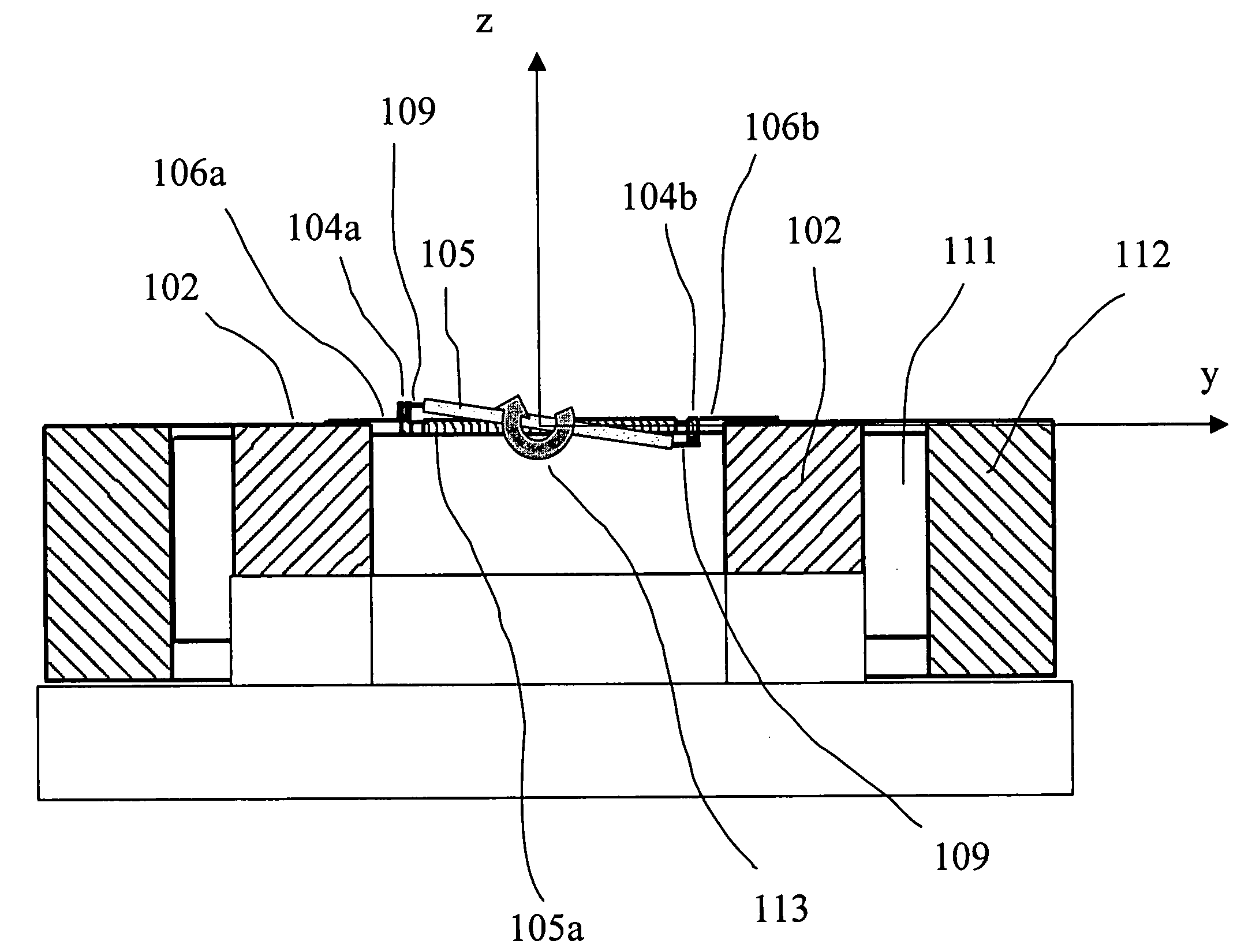
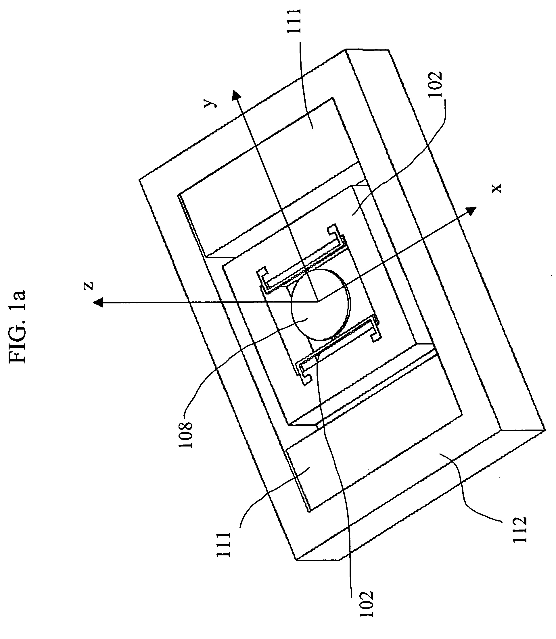
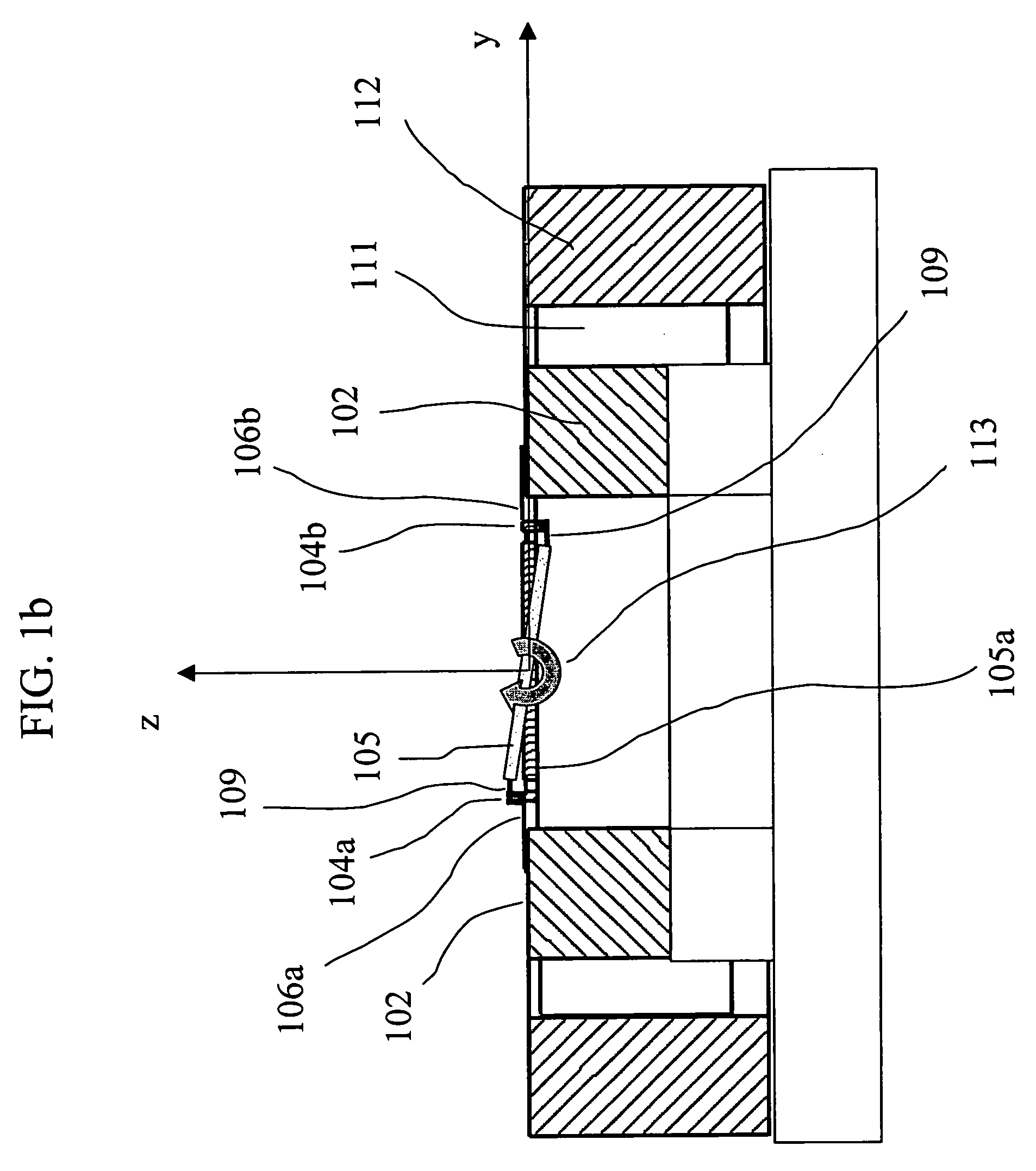
The present invention discloses magnetically electrically driven MEMS “plate type” mirrors and micro-scanners positioned in structures in which the magnetic or electromagnetic field is substantially parallel to the mirror plate. The mirrors may be categorized by symmetry as having either a symmetric or asymmetric design. They may be further. categorized as having, in either symmetry, one, two or three axes of rotation. The mirrors may be further categorized by their angular degrees of freedom as having either one DOF or two DOFs. The mirrors may be further categorized by their actuation mechanism as being driven by a single, double, triple or quadratic conductive flexural actuator (see definition below). A conductive flexural actuator according to the present invention may comprise one or more flexural members or beam springs, strips or leafs. Finally, the mirrors may be categorized by the arrangement of the actuators, which may be linear, triangular or square.

FIG. 1 shows schemat...


PUM


Abstract

Magnetically and electromagnetically driven MEMS devices for reflecting light signals and for switching radio frequency (RF) signals are provided. In a preferred embodiment, a light reflecting device such as a mirror or micro-scanner comprises a plate operative to reflect light and at least two conductive flexural actuators connected to the plate and to a substrate and operative to impart a rotation or tilt motion to the plate under a force arising from the interaction of a current passing through the conductive flexural actuators and a magnetic field parallel to the substrate. An RF switch comprises a substrate and a membrane having a longitudinal dimension and a lateral dimension, the membrane positioned substantially parallel to and attached to the substrate and operative to provide at least two switching positions in response to actuation by a Lorenz force acting on it.

Description

FIELD OF THE INVENTION The present invention related to miniaturized magnetically and electro-nagnetically actuated micro-electro-mechanical systems (MEMS) devices. In particular, the present invention refers to optical mirrors, optical scanners and radio-frequency (RF) switches, implemented in silicon using MEMS technologies and actuated by Lorentz forces. BACKGROUND OF THE INVENTION Miniaturized optical mirrors for industrial-scanning purposes, displays, direct writing, optical switching, etc. have been part of the MEMS (particularly Si-based) industry for some time. Specific applications may require mirrors with lateral dimensions of about 1 mm or more. Mirrors for optical applications in MEMS use mostly electrostatic actuation. However, several restrictions prevent the use of electrostatic driving for fast, high power, high-resolution and relatively large MEMS mirrors with large deflection angles. Technical difficulties arise during fabrication of large electrostatic mirrors w...

Claims


Application Information

Patent Timeline
Patent Type & Authority Applications(United States)
IPC IPC(8): G02B26/08
CPCG02B26/085G02B26/0833
Inventor BEN-GAD, ELIEZERMEDINA, MOSHEHERSHCOVITZ, MIRIAMHUBER, AVIGDORKRYLOV, SLAVA
Owner TERRAOP
Why Eureka
Try Eureka