
Compact pressurized water nuclear reactor

a nuclear reactor and compact technology, applied in nuclear reactors, reactor fuel elements, thermal reactors, etc., can solve the problems of inability to design high-power cores in this way, high investment costs, and inability to meet the needs of large-scale production,

Inactive Publication Date: 2005-01-27
COMMISSARIAT A LENERGIE ATOMIQUE ET AUX ENERGIES ALTERNATIVES
View PDF10 Cites 36 Cited by
  • Summary
  • Abstract
  • Description
  • Claims
  • Application Information

AI Technical Summary

Benefits of technology

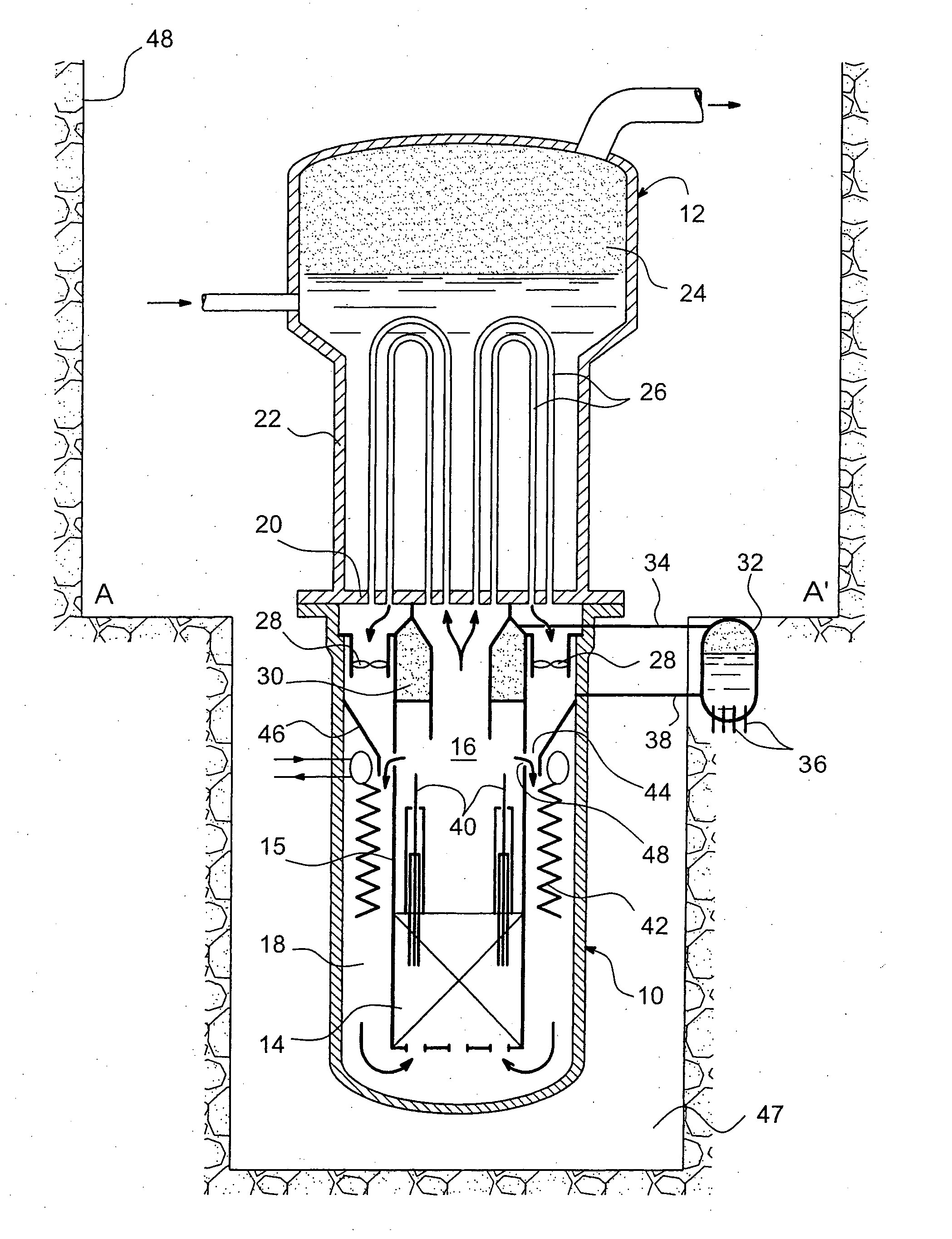
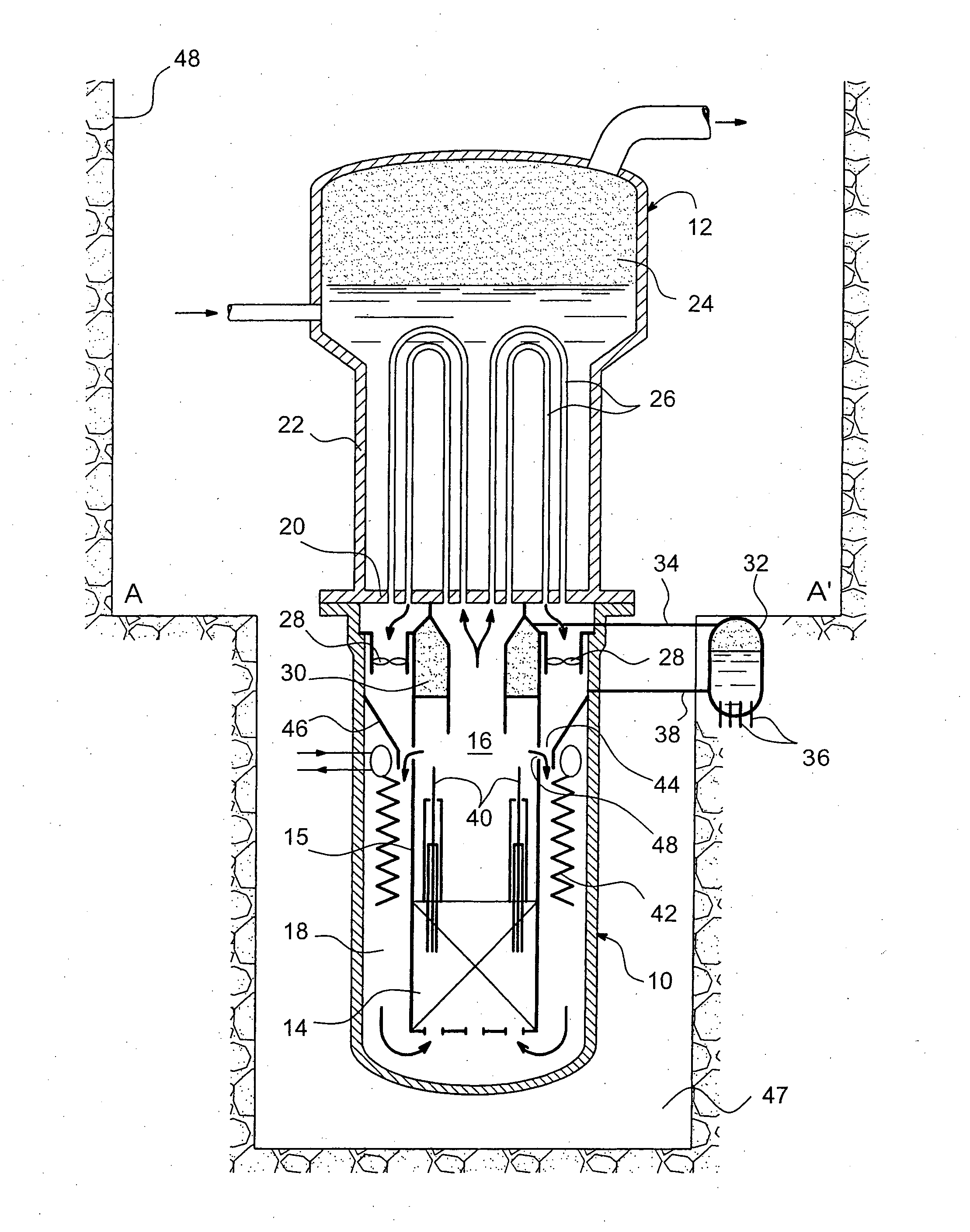
[0016] According to the invention, this objective is at least partially achieved by means of a compact pressurised water nuclear reactor comprising a vessel closed by a cover, a reactor core housed in the vessel, a steam generator forming the cover of the vessel, primary pumping means capable of making water circulate between the reactor core and the steam generator, and a pressuriser for pressurising water, characterised in that the pumping means and the pressuriser are housed in the reactor vessel so as to form a primary circuit fully integrated into the said vessel.
[0017] The fully integrated design of the reactor according to the invention reduces investment costs, particularly by simplifying the building architecture. This integrated design also eliminates a certain number of accident situations that are difficult to manage in terms of safety and for which expensive management systems are necessary.

Problems solved by technology

However, they have a number of disadvantages that are a direct result of their design.
A first disadvantage relates to their design.
The complexity of these devices makes it impossible to design high power cores in this way (more than 500 or 1000 MW thermal) due to the dimensions necessary for the large number of control rods.
A second disadvantage is their investment cost, particularly due to the architecture of buildings imposed by the design mentioned above.
Another disadvantage lies in the existence of a certain number of accident situations also inherent to the design of existing reactors.
These situations make a large number of protection and residual power evacuation systems necessary, which significantly increase the cost of these reactors.
Moreover, existing pressurised water nuclear reactors only enable the use of traditionally designed nuclear fuel assemblies.

Method used


Image

  • Compact pressurized water nuclear reactor
  • Compact pressurized water nuclear reactor

Examples


Embodiment Construction

[0025] As shown diagrammatically in the single figure, the compact pressurised water nuclear reactor according to the invention comprises a vessel 10 with a vertical axis.

[0026] The top end of the vessel 10 comprises an opening normally closed by a steam generator 12 thus forming the cover of the vessel.

[0027] The closed volume contained inside the vessel 10, below the cover materialised by the steam generator 12, is delimited on the inside by an approximately annular partition 15 that projects downwards from the said cover. The partition 15, centred on the vertical axis of the vessel 10, thus separates this closed volume into a central region 16 and a peripheral region 18, which communicate with each other through the bottom of the vessel 10.

[0028] The reactor core 14 is located in the bottom of the central region 16. It is formed from nuclear fuel assemblies arranged in bundles along a vertical direction. These assemblies may be of a conventional design or they may be of a diff...


PUM


Abstract

A compact pressurised water nuclear reactor comprises a primary circuit fully integrated into the reactor vessel (10). Thus, a single steam generator (12) forms the cover of the vessel (10) and the pressuriser (30) and the primary pumps (28) are housed in the vessel (10). The same is true for the control mechanisms of the control rods (40). Finally, a venturi system (44) is also provided in the vessel (10) to create water circulation if there is a failure of the primary pumps (28).

Description

TECHNICAL DOMAIN [0001] This invention relates to a pressurised water nuclear reactor with an integrated and compact design. [0002] The invention is particularly applicable to small and medium power nuclear reactors, in other words particularly reactors with a power less than or equal to approximately 600 MWe. STATE OF THE PRIOR ART [0003] Existing pressurised water nuclear reactors normally include a vessel containing the reactor core, primary circuits connecting the vessel to steam generators located outside the vessel, and primary pumps circulating pressurised water in each of the primary circuits, to transfer heat generated by the nuclear reaction in the reactor core, as far as the steam generators. A pressuriser, also located outside the vessel, pressurizes the water contained in the vessel and in the primary circuits. [0004] In these existing nuclear reactors, secondary circuits connect each of the steam generators to a turbine that drives an alternator to transform heat origi...

Claims


Application Information

Patent Timeline
Patent Type & Authority Applications(United States)
IPC IPC(8): G21C1/00G21C15/02G21C1/32G21C15/00G21C15/18G21C15/26
CPCG21C1/32G21C1/322Y02E30/40G21Y2004/305G21Y2002/301Y02E30/30G21C1/00
Inventor GAUTIER, GUY-MARIEPIGNATEL, JEAN-FRANCOIS
Owner COMMISSARIAT A LENERGIE ATOMIQUE ET AUX ENERGIES ALTERNATIVES
Learn More