System and process for calibrating a microphone array

a microphone array and microphone technology, applied in the direction of transducer details, electrical transducers, electrical apparatus, etc., can solve the problems of noise suppression or localization precision, the array used for beamforming or sound source localization does not provide the estimated shape of the beam, and the use of close-up microphones such as those installed on the headset is not very convenient,

Active Publication Date: 2005-01-27
MICROSOFT TECH LICENSING LLC
View PDF3 Cites 77 Cited by
  • Summary
  • Abstract
  • Description
  • Claims
  • Application Information

AI Technical Summary

Benefits of technology

The foregoing self calibration system and process has several advantages. For example, as indicated previously the simplification of the channel model and projection of sensors coordinates on the direction of arrival (DOA) line speed up the processing. Additionally, in one embodiment, audio frame sets are input only if the frames represent audio data exhibiting evidence of a single dominant sound source. This also speeds up processing and increases the accuracy of the self calibration. As a result, the calibration can be accomplished in what is effectively real time. Further, the refinement procedure allows the gain values to become stable over time, even in an environment with significant reverberation, and the aforementioned calibration suspension procedure decreases the processing costs of the present system and process even more. Yet another advantage of the present invention is that since the array sensors are not manually calibrated before operational use, changing conditions will not impact the calibration. For example, as microphone and preamplifier parameters depend on external factors as temperature, atmospheric pressure, the power supply, and so on, changes in these factors could invalidate any pre-calibration. Since the present calibration system and process continuously calibrates the microphone array during operation, changes in external factors are compensated for as they change. In addition, since changes in the microphone and preamplifier parameters can be compensated for on the fly by the present system and process, components can be replace without any significant effect. Thus, for example, a microphone can be replaced without replacing the preamplifier or manual recalibration. This is advantageous as significant portion of the cost of a microphone array is its preamplifiers.
is that since the array sensors are not manually calibrated before operational use, changing conditions will not impact the calibration. For example, as microphone and preamplifier parameters depend on external factors as temperature, atmospheric pressure, the power supply, and so on, changes in these factors could invalidate any pre-calibration. Since the present calibration system and process continuously calibrates the microphone array during operation, changes in external factors are compensated for as they change. In addition, since changes in the microphone and preamplifier parameters can be compensated for on the fly by the present system and process, components can be replace without any significant effect. Thus, for example, a microphone can be replaced without replacing the preamplifier or manual recalibration. This is advantageous as significant portion of the cost of a microphone array is its preamplifiers.
In addition to the just described benefits, other advantages of the present invention will become apparent from the detailed description which follows hereinafter when taken in conjunction with the drawing figures which accompany it.

Problems solved by technology

Using a close-up microphone, such as those installed on a headset, is not very convenient.
In addition, hands free sound capture with a single microphone is difficult due to interference with reflected sound waves.
However, in many cases microphone arrays used for beamforming or sound source localization do not provide the estimated shape of the beam, noise suppression or localization precision.
This is problematic as even a basic algorithm as delay-and-sum procedure is sensitive to mismatches in the receiving channels.
More sophisticated algorithms for beamforming are even more susceptible and often require very precise matching of the impulse response of the microphone-preamplifier-ADC (analog to digital converter) combination for all channels.
The problem is that without careful calibration a mismatch in the microphone array audio channels is hard to avoid.
The looseness in the tolerances associated with components used in the microphone array preamplifiers introduces gain and phase errors as well.
Generally, current calibration procedures can be an expensive and difficult task, particularly for broadband arrays.
This approach is very expensive as it requires manual calibration for each microphone, as well as specialized equipment to accomplish this task.
Thus, they too can be time consuming and expensive to accomplish.
In addition, as these calibration methods are done ahead of time, they will not remain valid in the face of changes in the equipment and environmental conditions during operation.
In some cases the complexity of the estimation algorithms makes them unsuitable for practical real-time implementation due to the fact that they require an excessive amount of CPU power during the normal operation of the microphone array.

Method used


Image

  • System and process for calibrating a microphone array
  • System and process for calibrating a microphone array
  • System and process for calibrating a microphone array

Examples


Embodiment Construction

In the following description of the preferred embodiments of the present invention, reference is made to the accompanying drawings which form a part hereof, and in which is shown by way of illustration specific embodiments in which the invention may be practiced. It is understood that other embodiments may be utilized and structural changes may be made without departing from the scope of the present invention.

1.0 The Computing Environment

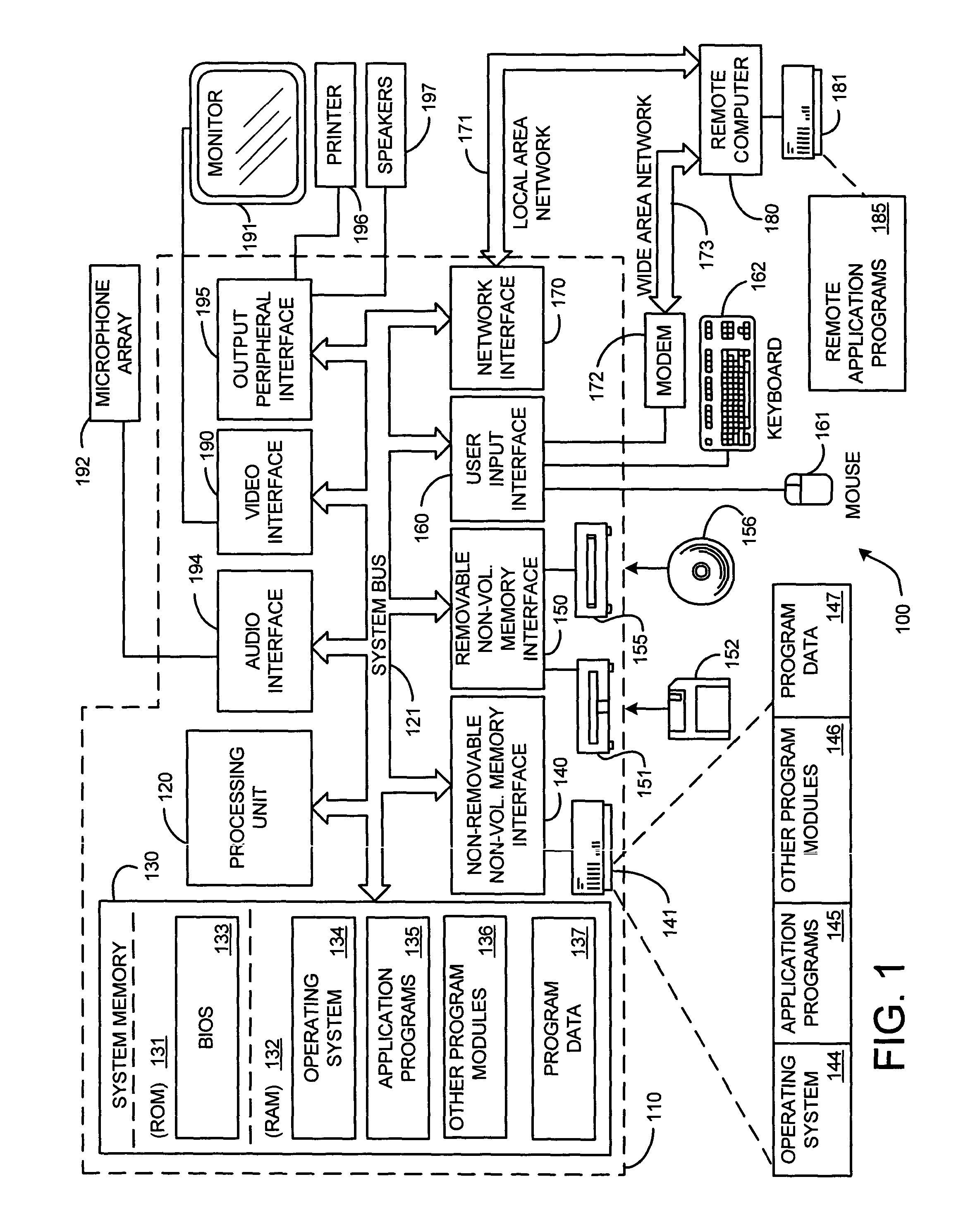
Before providing a description of the preferred embodiments of the present invention, a brief, general description of a suitable computing environment in which the invention may be implemented will be described. FIG. 1 illustrates an example of a suitable computing system environment 100. The computing system environment 100 is only one example of a suitable computing environment and is not intended to suggest any limitation as to the scope of use or functionality of the invention. Neither should the computing environment 100 be interpreted as ...


PUM


Abstract

A system and process for self calibrating a plurality of audio sensors of a microphone array on a continuous basis, while the array is in operation, is presented. In essence, the present microphone array self calibration system and process finds a set of corrective gains that provides the best channel matching amongst the audio sensors of the array by compensating for the differences in the sensor parameters. The present system and process is not CPU use intensive and is capable of providing real-time microphone array self-calibration. It is based on a simplified channel model, projection of sensor coordinates on the direction of arrival (DOA) line, and approximation of received energy levels, all of which speed up processing time.

Description

BACKGROUND 1. Technical Field The invention is related to the calibration of microphone arrays, and more particularly to a system and process for self calibrating a plurality of audio sensors of a microphone array on a continuous basis, while the array is in operation. 2. Background Art With the burgeoning development of sound recognition software and real-time collaboration and communication programs, the ability to capture high quality sound is becoming more and more important. Using a close-up microphone, such as those installed on a headset, is not very convenient. In addition, hands free sound capture with a single microphone is difficult due to interference with reflected sound waves. In some cases frequencies are enhanced and in others frequencies can be completely suppressed. One emerging technology used to effectively capture high quality sound is the microphone array. A microphone array is made up of a set of microphones positioned closely together, typically in a patt...

Claims


Application Information

Patent Timeline
Patent Type & Authority Applications(United States)
IPC IPC(8): H04R3/00
CPCH04R1/406H04R2201/401H04R3/005
Inventor TASHEV, IVAN
Owner MICROSOFT TECH LICENSING LLC
Why Eureka
Try Eureka