Method of flow forming a metal part

a metal part and flow forming technology, applied in mechanical equipment, transportation and packaging, hoisting equipment, etc., can solve the problems of metal process, reduced strength of parts, and inability to compact powder metal to 100% density of material, and achieve the effect of eliminating powder metal porosities and great accuracy

Inactive Publication Date: 2005-01-27
THE GATES CORP
View PDF17 Cites 10 Cited by
  • Summary
  • Abstract
  • Description
  • Claims
  • Application Information

AI Technical Summary

Benefits of technology

[0018] Another aspect of the invention is to provide a method of manufacturing low cost, net-shaped, high inertia pulleys for crankshaft dampers by flow forming sintered or cast metal parts.
[0020] A method of flow forming sintered metal parts. The first step is forming a round disk by conventional powder metal process. The disk can be a donut shape part with or without a flange on one side of its outer diameter. The disk can then be copper impregnated or used as is, depending on the requirements. The disk is placed in a spinner held in proper tooling and grooves are spun in its outer diameter. The spinning can be done with a finishing roller or by a pre-finishing roller, followed by a finishing roller. This process not only creates a part with great accuracy, it also densifies and eliminates the powder metal porosities in the entire groove structure and on the surface layer by the pressures inserted in spinning.

Problems solved by technology

There are two inherent disadvantages to powder metal process.
The first problem is that it is very difficult, if not impossible, to compact the powder metal to 100% density of the material to eliminate all voids and porosities.
Voids reduce the strength of the part and can also create internal corrosion.
Resin impregnation has limited applications because it does not increase material properties and the resin melts down at low temperatures, for example, in a painting oven.
Copper impregnation, while adding to the material strength, is costly and more importantly creates dimensional changes to the part reducing the dimensional accuracy.
The second problem with powder metal process is that the capability of compacting the powder in the horizontal direction, perpendicular to the compaction force, is very limited.
This means that current products like multiple ribbed pulley grooves cannot be made by a powder metal / sinter process, while sprocket teeth can be manufactured using a powder metal / sinter process.
However, for crankshaft damper pulleys, in many cases the mass of the pulley has to be higher than what spun sheet metal pulleys can provide.
The problem with cast iron is that due to its manufacturing process, i.e. cast in sand, it has to be machined to achieve the desired final shape and dimension.
Machining is a relatively expensive operation as it adds time and labor costs as well as creating waste.
Furthermore, machined grooves of a multiple ribbed or other types of pulleys are rougher than a spun part due to the existence of machining marks (grooves) caused by the cutting head.
This leads to decreased belt life.
Furthermore, machining exposes porosities, which are inherent in castings.
The sharp edges of open porosities are detrimental to a belt running on the grooves.

Method used


Image

  • Method of flow forming a metal part
  • Method of flow forming a metal part
  • Method of flow forming a metal part

Examples


Embodiment Construction

[0026] Powder metal (PM) is a known method of manufacturing ferrous and nonferrous parts. First, elemental or alloy powders are mixed and compacted in a die. The resultant shapes are then sintered or heated in a controlled-atmosphere furnace to metallurgically bond the particles. PM is generally a low waste metalworking process, typically using more than 97% of the starting raw material in the finished part. As a result PM is an energy and materials conserving process. Although PM is capable of producing parts to final dimensions, some finish machining is usually required to bring a part to a final high accuracy.

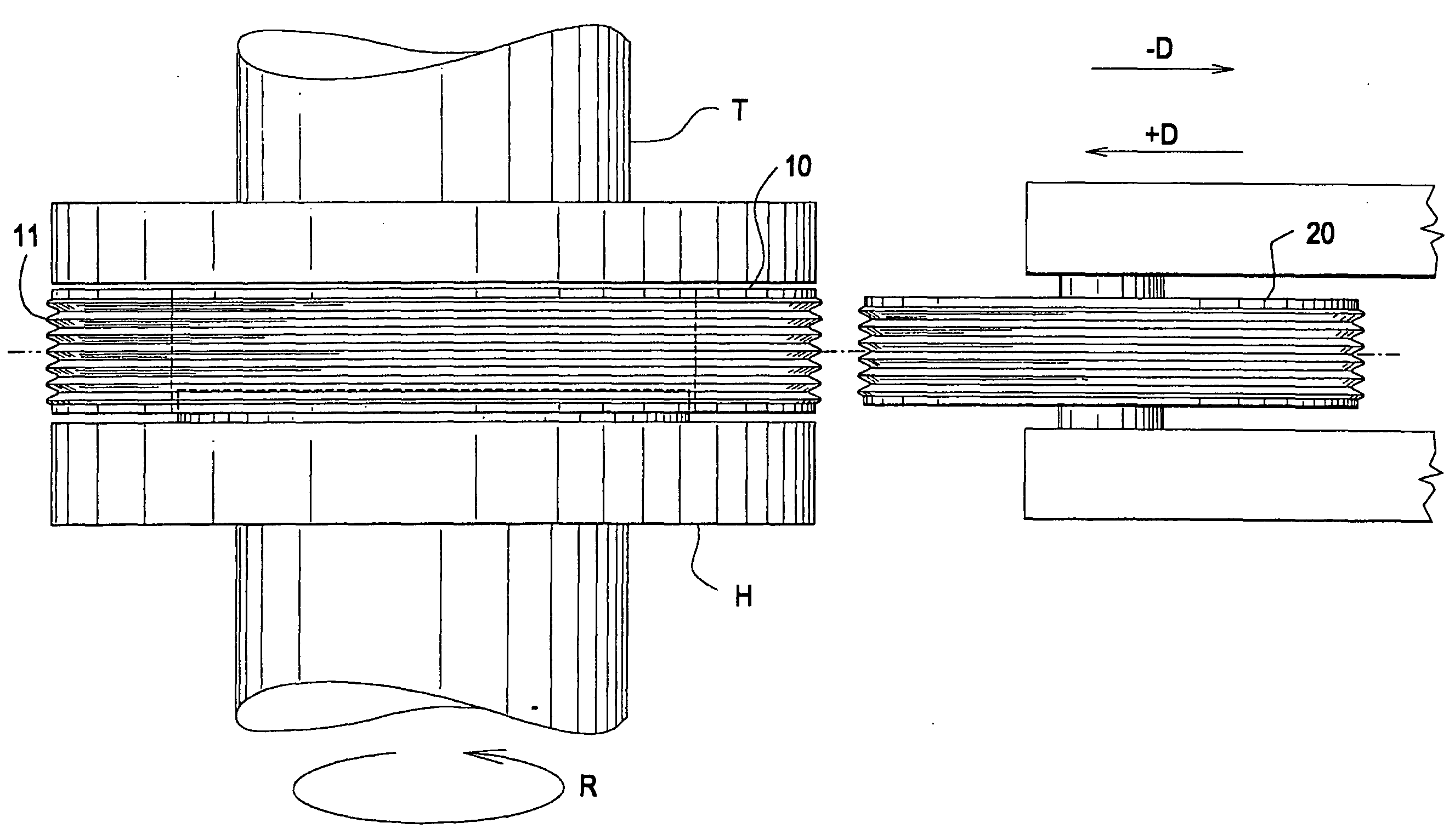
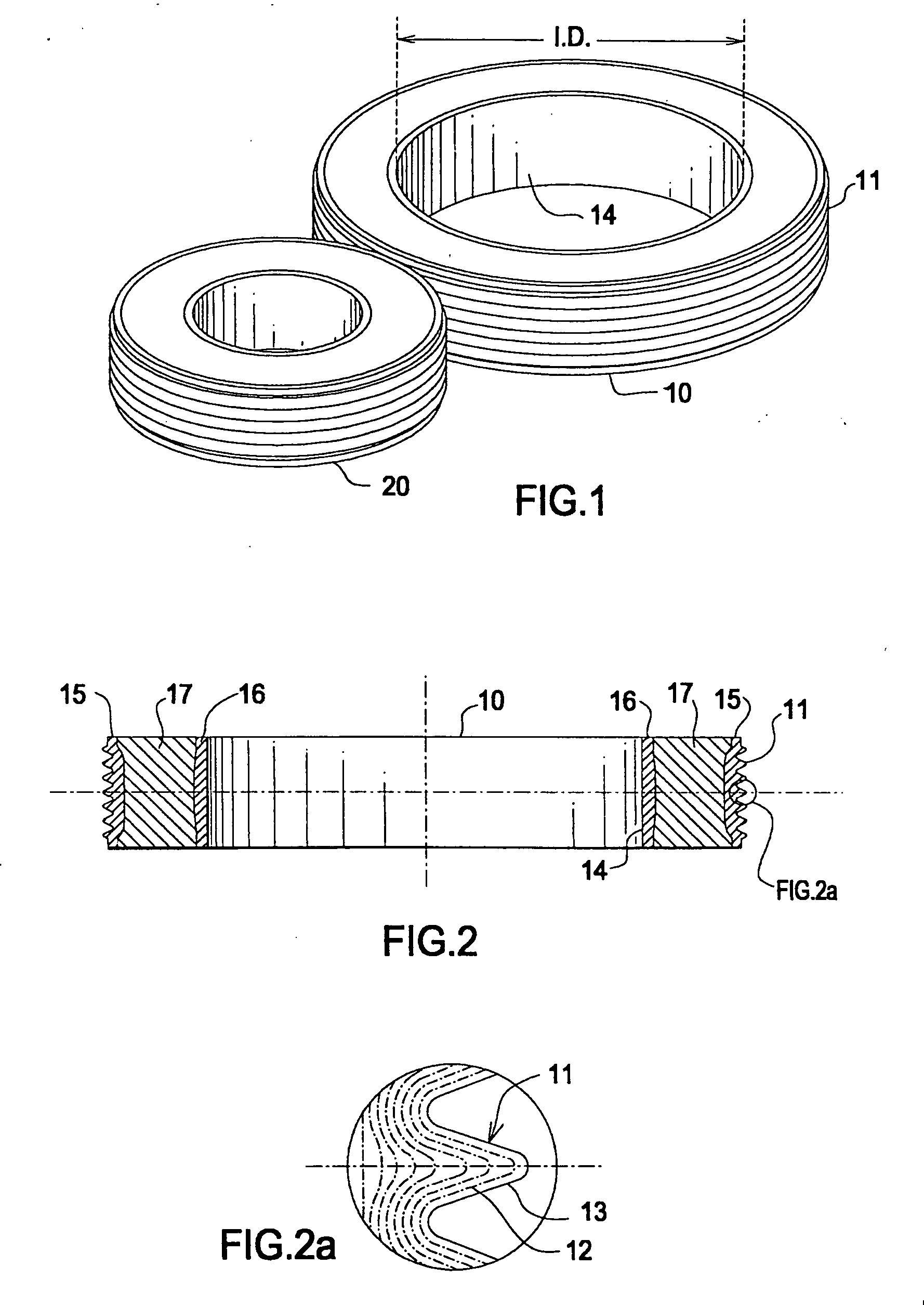
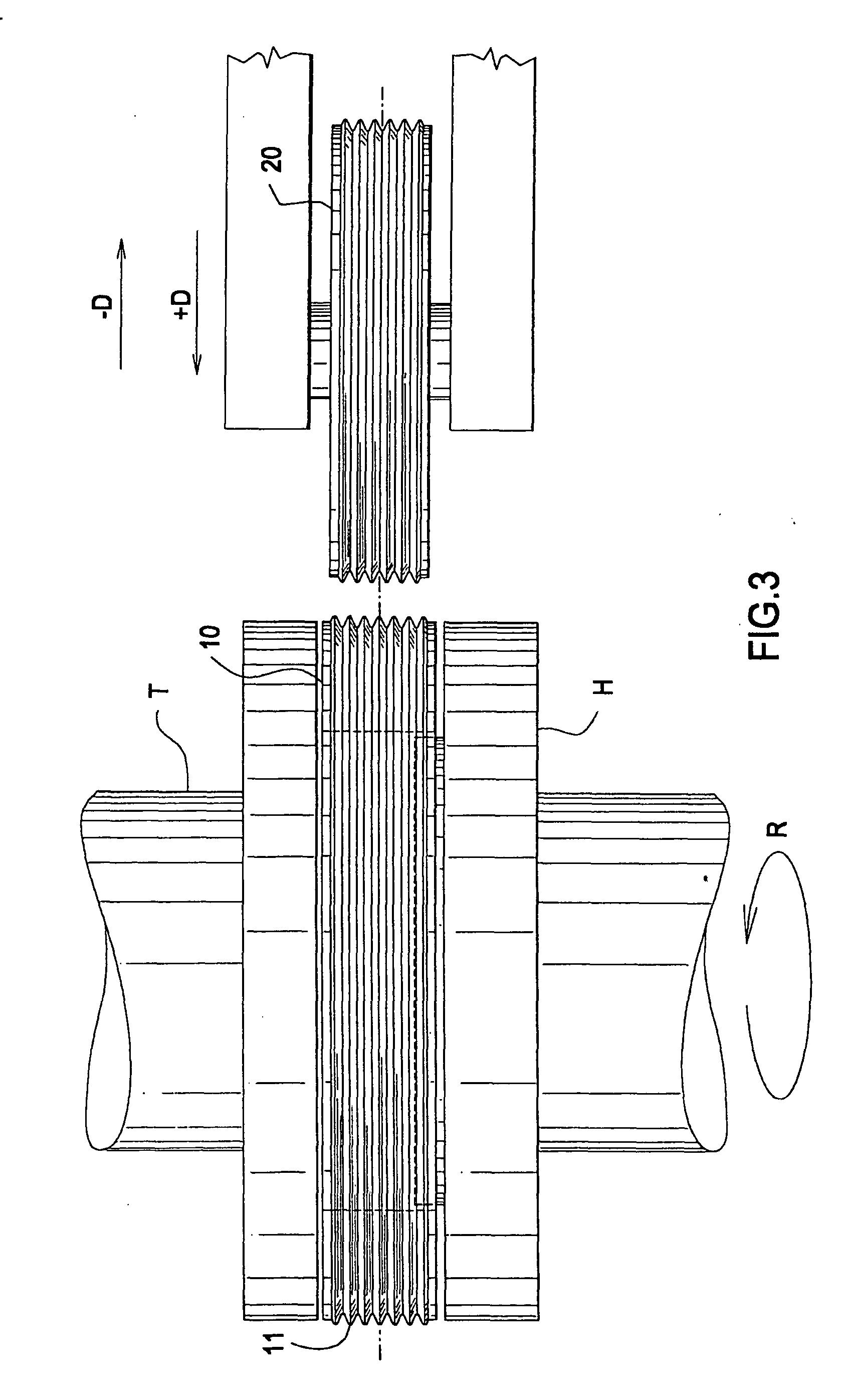
[0027] The first step of the inventive process is forming a round disk by conventional powder metal process. The disk can be a donut shaped part with or without a flange on one side of its outer diameter, see FIG. 1. Although flanges can be made on both sides of the outer diameter of the blank, it is a more difficult process in powder metal, requiring a cam action in the di...


PUM

PropertyMeasurementUnit
temperatureaaaaaaaaaa
thicknessaaaaaaaaaa
thicknessaaaaaaaaaa

Abstract

A method of flow forming sintered metal parts. The first step is forming a round disk by conventional powder metal process. The disk can be a donut shape part with or without a flange on one side of its outer diameter. The disk can then be copper impregnated or used as is, depending on the requirements. The disk is placed in a spinner held in proper tooling and grooves are spun in its outer diameter. The spinning can be done with a finishing roller or by a pre-finishing roller, followed by a finishing roller. This process not only creates a part with great accuracy, it also densifies and eliminates the powder metal porosities on the surface layer by the pressures inserted in spinning.

Description

FIELD OF THE INVENTION [0001] The invention relates to a method of flow forming a metal part, namely, a sintered or cast metal part. BACKGROUND OF THE INVENTION [0002] Powder metal manufacturing is a known process. Fine particles of metal powder are compacted to the desired shape and subsequently sintered in a furnace. Sintering causes melting and welding of powder particles on their respective surfaces to form a part. [0003] There are two inherent disadvantages to powder metal process. The first problem is that it is very difficult, if not impossible, to compact the powder metal to 100% density of the material to eliminate all voids and porosities. Voids reduce the strength of the part and can also create internal corrosion. The solution to this problem is impregnation, or infiltration, of the voids by copper, resin, or other material. Resin impregnation has limited applications because it does not increase material properties and the resin melts down at low temperatures, for examp...

Claims


Application Information

Patent Timeline
Patent Type & Authority Applications(United States)
IPC IPC(8): B21D53/26B21H1/04B22F3/18F16H55/36
CPCB21D53/261B21H1/04B22F3/164B22F3/18B22F2998/10F16H55/36B22F3/02B22F3/10B22F3/24
Inventor HODJAT, YAHYA
Owner THE GATES CORP
Why Eureka
Try Eureka