Fuel cell collector structure and solid oxide fuel cell stack using the same

Active Publication Date: 2005-01-27
NISSAN MOTOR CO LTD
View PDF3 Cites 16 Cited by
  • Summary
  • Abstract
  • Description
  • Claims
  • Application Information

AI Technical Summary

Benefits of technology

[0012] The present invention has been achieved in view of the above problems in the conventional technique, and it is an object of the present invention to provide a fuel cell collector structure having a good electrical c

Problems solved by technology

However, in the technique described in Japanese Patent Application Laid-Open No. 2001-68132, because a countermeasure of thickening the cell and the like are required in order to secure strength of the cell so as not to break the cell, the stack becomes heavy and large.
This does not satisfy the lightness and the compactness, which are requirements of a vehicle.
H1-012469,

Method used


Image

  • Fuel cell collector structure and solid oxide fuel cell stack using the same
  • Fuel cell collector structure and solid oxide fuel cell stack using the same
  • Fuel cell collector structure and solid oxide fuel cell stack using the same

Examples


example 1

[0065]FIGS. 9A, 9B, and 9C show the single cell constituting the fuel cell collector structure of Example 1 and the collector arranged in the single cell. The cell shown in FIGS. 9A to 9C is an electrolyte support type in which the electrolyte layer is a support substrate.

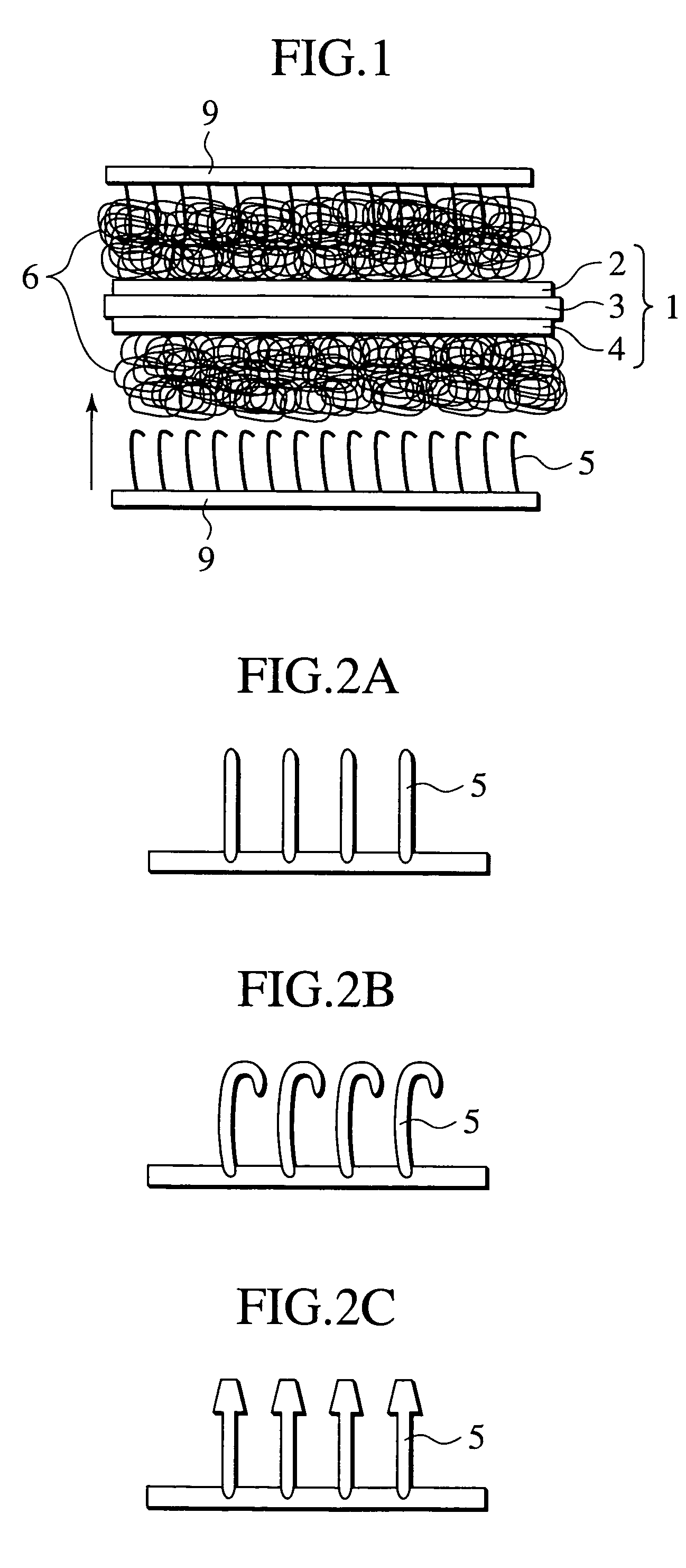
[0066] The single cell 1 of Example 1 was formed by sandwiching the both surfaces of the electrolyte layer 3 between the air electrode layer 2 and the fuel electrode layer 4. The electrolyte layer 3 was made of 8 mol % yttria-stabilized zirconia (8YSZ) having the dimensions of about 12 cm square and the thickness of 100 μm. The electrolyte layer 3 included a support portion 3a in which a gas sealing portion and the gas passage were formed, while supporting the cell when the electrode was formed to be stacked with another single cell.

[0067] The air electrode layer 2 and the fuel electrode layer 4 had the dimensions of about 10 cm square, and the air electrode layer 2 and the fuel electrode layer 4 were baked in th...

example 2

[0081] The fuel cell stack having the structure shown in FIG. 8 was produced and variation of the output was measured. The single cell 1 used in Example 2 was one in which the fuel electrode layer 4 made of NiO-8YSZ having the dimensions of 10 cm square and the thickness of 10 μm and the air electrode layer 2 made of La0.8Sr0.2MnO3 having the dimensions of 10 cm square and the thickness of 10 μm were provided on the electrolyte plate made of 8YSZ having the dimensions of 12 cm square and the thickness of 50 μm.

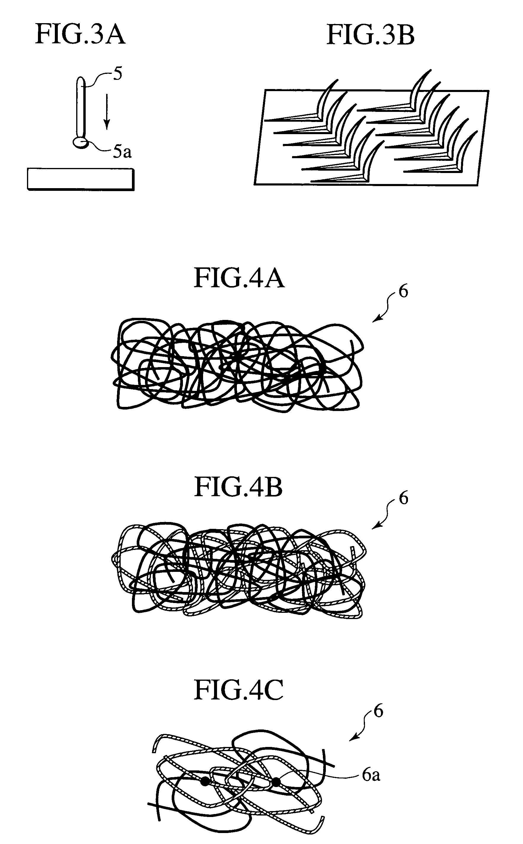
[0082] About 5% Pt fiber having the excellent heat resistance, oxidizing atmosphere resistance, and reduction atmosphere resistance was baked as the electrically conductive projection 5 on the surfaces of both the electrodes at the same time when the electrode layer was formed.

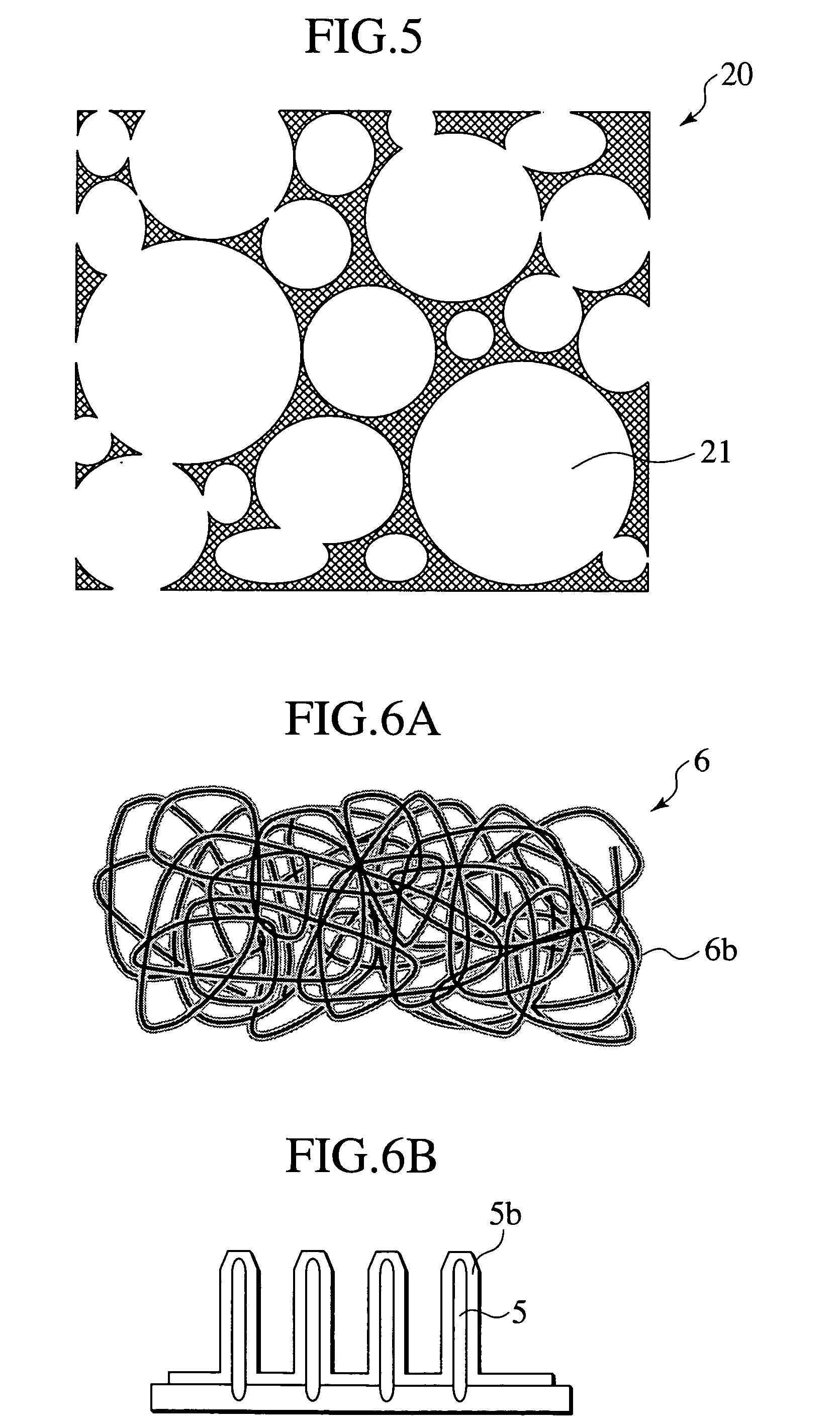
[0083] The metal felt made of the Ni metal thin wire having the diameter of 20 μm was used as the collector 6 on the fuel electrode layer 4 side. Further, the porous electric conductor made of the meta...

example 3

[0087] The collector structure of Example 3 was obtained by repeating the same procedure as Example 1 except that the electrically conductive projections 5 on the single cell 1 were formed by the plating. FIG. 17 shows the enlarged view of the collector structure, and FIGS. 18A to 18D show the process of producing the collector structure.

[0088] As shown in FIG. 18A, the fuel electrode layer and the air electrode layer were respectively baked on the surfaces of the electrolyte layer made of 8YSZ to produce the single cell 1.

[0089] As shown in FIG. 18B, after the electrically conductive material such as Pt was deposited on both the surfaces of the single cell 1 with the thickness of about 100 nm, both the surfaces were coated with resist films 12, and the aperture portions in which a Pt layer is exposed at the predetermined position were formed by a photolithographic technology.

[0090] As shown in FIG. 18C, the electrically conductive projections 5 made of Pt were formed on the surf...


PUM


Abstract

A fuel cell collector structure of the present invention includes a single cell which is formed by sandwiching a plate-shaped solid electrolyte between a fuel electrode and an air electrode, a collector which is provided at a position adjacent to the single cell, and a separator which is provided at the position adjacent to the collector. In the fuel cell collector structure, the collector is made of a porous electric conductor having a plurality of apertures on a surface, the single cell and/or the separator has a plurality of electrically conductive projections on the surface, and the projections intrude into the apertures to come into contact with the collector.

Description

BACKGROUND OF THE INVENTION [0001] 1. Field of the Invention [0002] The present invention relates to a fuel cell collector structure and a solid oxide fuel cell stack using the same. More particularly, the invention relates to the fuel cell collector structure which secures electric conduction between plate-shaped single cells and prevents a decrease in conductivity characteristics of a single cell by deformation caused by temperature change, and also relates to the solid oxide fuel cell stack using the same. [0003] 2. Description of the Related Art [0004] Recently, the fuel cell receives attention from a viewpoint of resource saving and environmental protection. In the fuel cell, air and hydrogen are respectively used as oxidizing agent gas and fuel gas to directly convert latent chemical energy of the fuel into electric energy. Particularly, because a solid oxide fuel cell (SOFC) has many advantages such that electric power generation efficiency is high and waste heat is effective...

Claims


Application Information

Patent Timeline
IPC IPC(8): H01M4/86H01M8/02H01M8/12H01M8/24
CPCH01M4/8621H01M4/8626H01M8/0232Y02E60/525H01M8/2425H01M2008/1293Y02E60/50H01M8/0247H01M8/2432H01M8/2483H01M8/026
Inventor HISHITANI, YOSHIKOSHIBATA, ITARUSATOU, FUMINORIKUSHIBIKI, KEIKONAKAJIMA, YASUSHIIBUKA, SHIGEO
Owner NISSAN MOTOR CO LTD
Why Eureka
Try Eureka