Random array of microspheres

a random array and microsphere technology, applied in the field of biological or sensor microarray technology, can solve the problems of the inability to accurately predict the effect of the microsphere, so as to facilitate the access of the analyte, facilitate the preparation, and reduce the cost of the method

Inactive Publication Date: 2005-01-27
CARESTREAM HEALTH INC
View PDF17 Cites 14 Cited by
  • Summary
  • Abstract
  • Description
  • Claims
  • Application Information

AI Technical Summary

Benefits of technology

The invention utilizes a unique coating technology to prepare a micro-array on a substrate that need not be pre-etched with microwells or premarked in any way with sites to attract the microspheres, as disclosed in the art. By using unmarked substrates or substrates that need no pre-coating preparation, the present invention provides a huge manufacturing advantage compared to the existing technologies. The invention discloses a method whereby addressable mixed microspheres in a dispersion are randomly distributed on a receiving layer that has no wells or sites to attract the microspheres.
The present invention provides a micro-array that is less costly and easier to prepare than those previously disclosed because the substrate does not have to be modified; nevertheless the microspheres remain immobilized on the substrate.
Further, the present invention provides a micro-array wherein, in contrast to U.S. Ser. No. 09/942,241,

Problems solved by technology

This method is expensive.
An ink jet approach is being used by others (e.g., U.S. Pat. Nos. 6,079,283; 6,083,762; and 6,094,966) to fabricate spatially addressable arrays, but this technique also suffers from high manufacturing cost in addition to the relatively large spot size of 40 to 100 μm.
Because the number of bioactive probes to be placed on a single chip usually runs anywhere from 1,000 to 100,000 probes, the spatial addressing method is intrinsically expensive regardless of how the chip is manufactured.
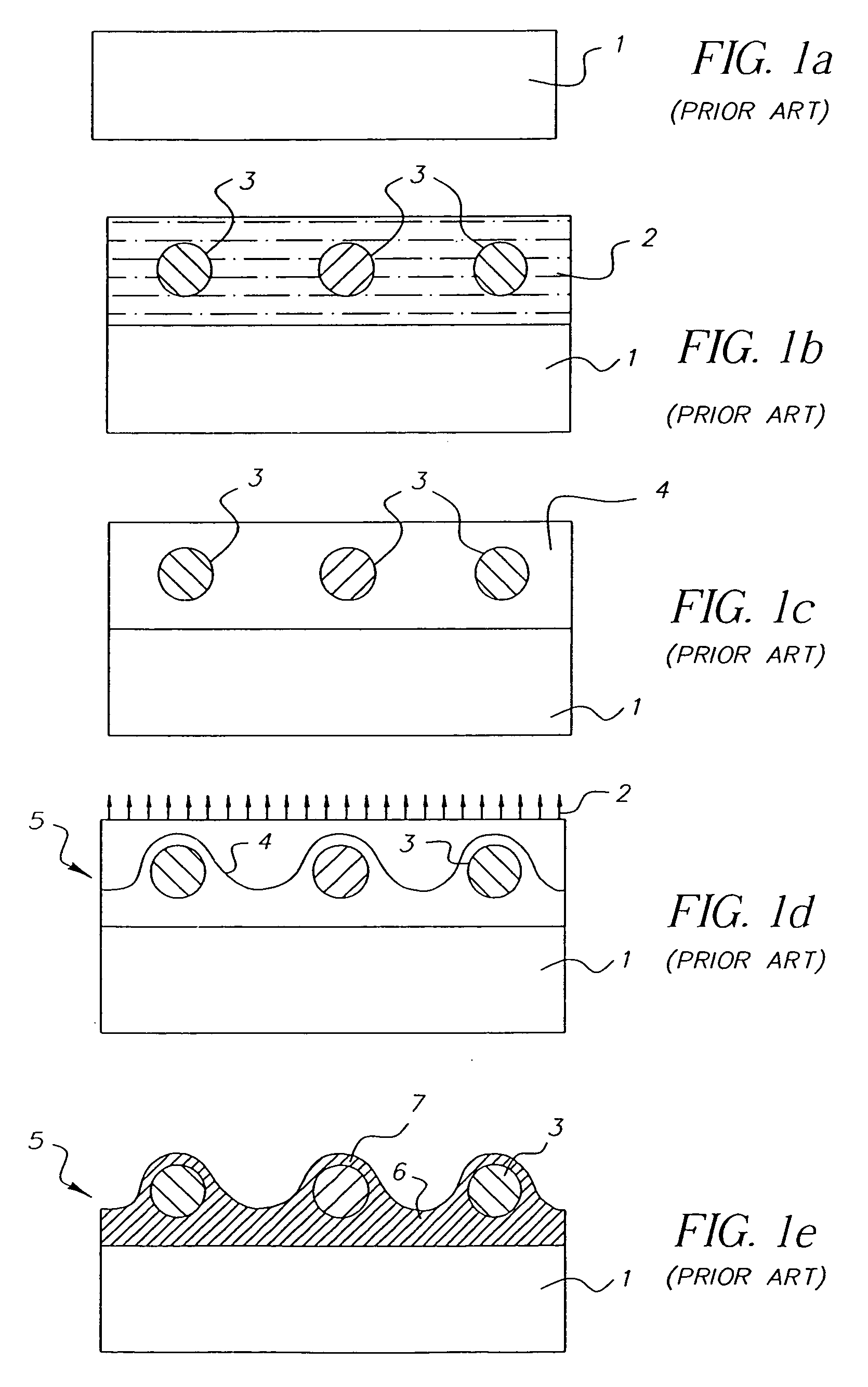
The problem is that during such machine coating and rapid gelation, the gelling agent tends to cover the surface of the microspheres as shown in FIG. 1e, thereby preventing the analyte (such as DNA) from penetrating through the gel overcoat and hybridizing

Method used


Image

  • Random array of microspheres
  • Random array of microspheres
  • Random array of microspheres

Examples


examples

In the following example, Monte Carlo simulations as described in “Random Number Generation and Monte Carlo Methods (Statistics & Computing)” by James E. Gentle, Springer Verlag (1998), are performed to determine the distance between the microspheres that were introduced randomly. The results are then utilized in an analysis to calculate the Young's modulus of the receiving layer that avoids lateral aggregation of microspheres To simulate a random distribution of microspheres as achieved by the invention, 1000 microspheres of 10μ diameter were randomly dropped over a substrate with an area of 1 cm2, such that no two of the microspheres overlapped, as shown in FIG. 6. The distribution of nearest neighbor separation distances between the microspheres in FIG. 6 is shown in Table 1 and is plotted in FIG. 7. The microspheres were randomly dropped on the substrate 20 times, and the average over all twenty simulations is shown in Table 2. A cumulative average for each of the nearest neigh...


PUM

PropertyMeasurementUnit
Pressureaaaaaaaaaa
Diameteraaaaaaaaaa
Coloraaaaaaaaaa

Abstract

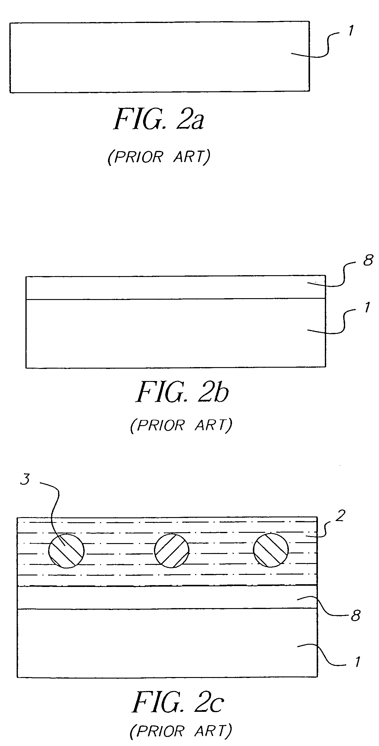
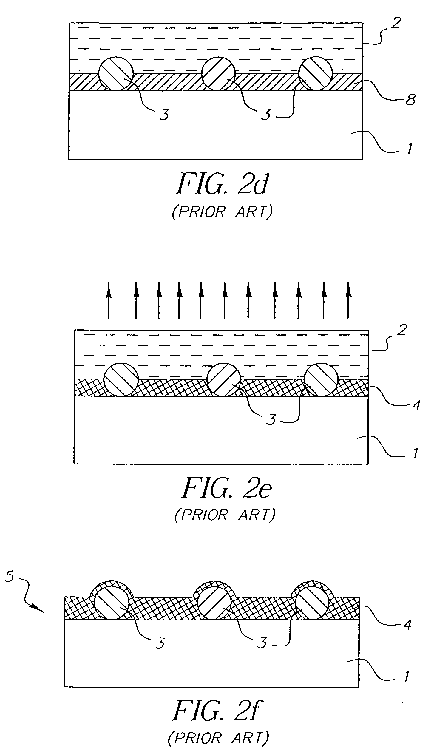
An element containing an array of microspheres on a support is described, and a method of making the element, wherein the method includes coating a support with a coating composition to form a receiving layer with a modifiable elastic modulus; coating on the receiving layer a dispersion of microspheres in a fluid suspension; modifying the modulus of the receiving layer to allow the microspheres to partially submerge into the receiving layer; removing the fluid suspension from the receiving layer; and fixing the microspheres in the receiving layer so that the element can withstand wet processing.

Description

FIELD OF THE INVENTION The present invention concerns biological or sensor micro-array technology in general. In particular, it concerns a micro-array coated on a substrate that contains no sites designated to attract the microspheres prior to coating. BACKGROUND OF THE INVENTION Ever since they were invented in the early 1990s, high-density arrays formed by spatially addressable synthesis of bioactive probes on a two-dimensional solid support have greatly enhanced and simplified the process of biological research and development (see Science, 251, 767-773, 1991). The key to current micro-array technology is deposition of a bioactive agent at a single spot on a microchip in a “spatially addressable” manner. Current technologies have used various approaches to fabricate micro-arrays. For example, U.S. Pat. Nos. 5,412,087, and 5,489,678 demonstrate the use of a photolithographic process for making peptide and DNA micro-arrays. The patents teach the use of photolabile protecting gro...

Claims


Application Information

Patent Timeline
IPC IPC(8): B01J19/00C40B40/06C40B40/10C40B70/00G01N33/543
CPCB01J19/0046B01J2219/00466B01J2219/00545B01J2219/00596B01J2219/00648G01N33/54393B01J2219/00725C40B40/06C40B40/10C40B70/00G01N33/5432B01J2219/00722
Inventor CHARI, KRISHNANGAO, ZHANJUNSEDITA, JOSEPH S.HANUMANTHU, RAMASUBRAMANIAMLUSIGNAN, CHARLES P.
Owner CARESTREAM HEALTH INC
Why Eureka
Try Eureka