Multilayer textile reinforcement web

Inactive Publication Date: 2005-01-27
MAGNELL CARL O +1
View PDF5 Cites 13 Cited by
  • Summary
  • Abstract
  • Description
  • Claims
  • Application Information

AI Technical Summary

Benefits of technology

[0005] Multilayer textile webs offer a broad spectrum of uses, characterized by extensive applications of synthetic fiber reinforced panels for walls, floors, balconies, roofing; as sandwich panels for curtain walls with natural or synthetic stone; as sealing panels for sub-surface construction; and as reinforcement for large concrete components with corroded steel reinforcement. Other applications include: large sewer pipes, water pipes, reinforced steam pipes, rotors and bases for wind-powered generators, marine hulls, superstructures and internal load bearing components, cargo containers, overhead cranes, rail

Problems solved by technology

The possible applications are, however, limited when large parts must be fabricated (especially with the use of glass fibers) for example, in railcars, marine vessels, or in buildings, especially facades and roofs.
The most significant drawbacks of limited reinforcement web width are: (i) the inevit

Method used


Image

  • Multilayer textile reinforcement web
  • Multilayer textile reinforcement web
  • Multilayer textile reinforcement web

Examples


Embodiment Construction

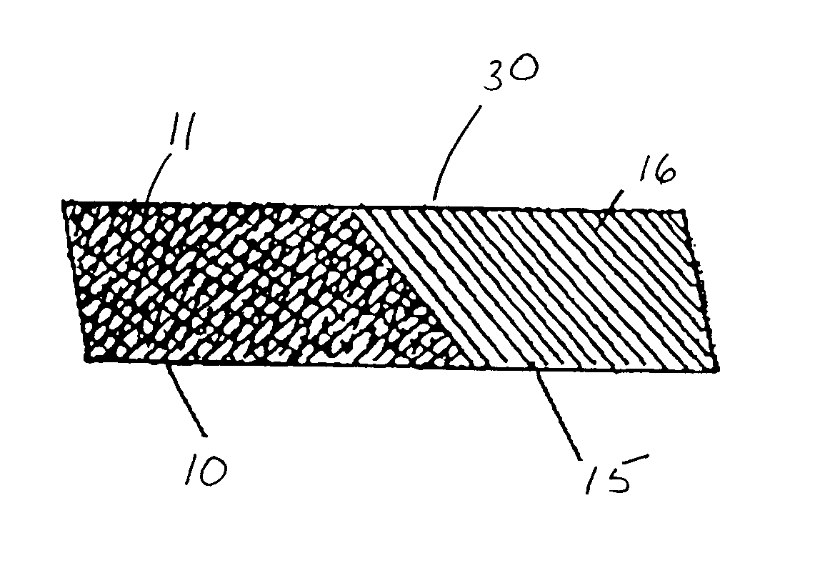
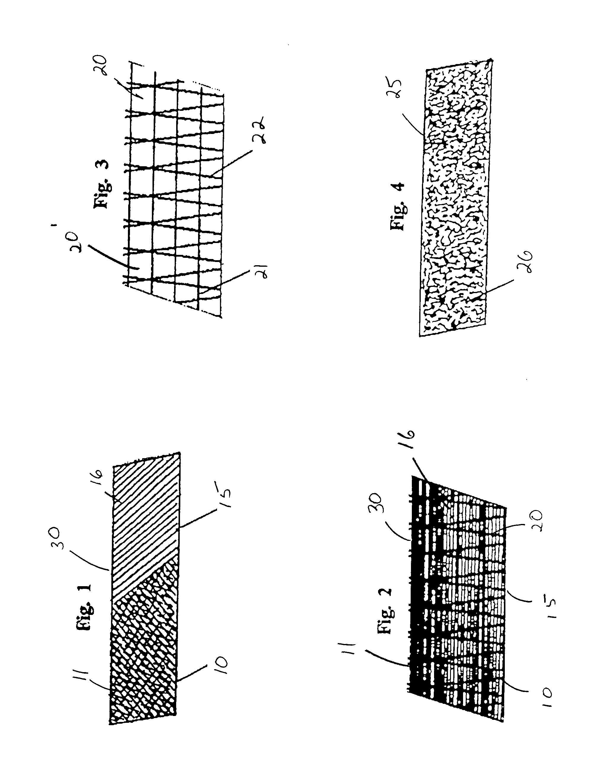
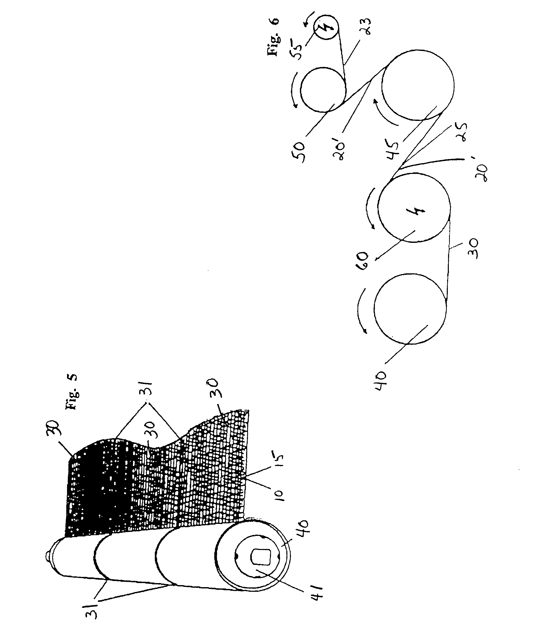
[0013] Referring to the drawings in detail wherein like elements are indicated by like numerals, the purpose of the present invention is to overcome drawbacks that accrue from both limited web widths and limited web connection strength. To achieve this, two single webs 10, 15 are glued together. In other embodiments of the invention, more than two single webs may be used. FIG. 1 illustrates two single webs 10, 15 attached to each other, the first web 10 having fiber strands 11 in ±45° fiber orientations and the second web 15 having fiber strands 16 arranged in parallel. FIG. 2 illustrates two single webs 10, 15 having fiber strands 11, 16 arranged in parallel. The chosen single webs 10, 15 are then glued together with adhesive threads 20. As may be best seen in FIG. 3, an adhesive thread grid 20 with longitudinal threads 21 and transverse threads 22 may be used. The threads 21, 22 may be composed of glass, carbon, aramid, polyester, spun rayon and similar fibers. The single webs 10,...


PUM

PropertyMeasurementUnit
Angleaaaaaaaaaa
Adhesivityaaaaaaaaaa
Tensionaaaaaaaaaa

Abstract

Multiple, single fiber webs, consisting of parallel fiber bundles and non-wovens connected by an adhesive thread grid, positioned on a common shaft for simultaneous unwinding. The single webs are dispensed under tension from a primary unwinding drum while, in the same process, an additional adhesive thread grid of non-woven or fiber mat is dispensed and, using tension winding, combined with the single webs into a homogeneous laminate.

Description

BACKGROUND OF THE INVENTION [0001] This invention relates to reinforcing articles, and in particular to multilayer textile reinforcement webs. [0002] Uni-directional and multi-directional textile webs have proven themselves particularly as outstanding reinforcements. Currently manufactured textile webs, comprised of parallel oriented fiber bundles, are available only in limited web widths. The possible applications are, however, limited when large parts must be fabricated (especially with the use of glass fibers) for example, in railcars, marine vessels, or in buildings, especially facades and roofs. The largest possible web widths are desired by web users, for example, in construction applications, in order to minimize costs and obtain maximum total strength over large surfaces without the use of butt joints. [0003] The most significant drawbacks of limited reinforcement web width are: (i) the inevitable occurrence of gaps between adjacent webs that prevent a consistently strong co...

Claims


Application Information

Patent Timeline
IPC IPC(8): B32B5/26B32B7/03B32B37/20D04H13/00
CPCB32B5/26Y10T428/24058B32B2037/123B32B2305/18B32B2305/28D04H3/04D04H3/12D04H13/00Y10T156/10Y10T428/197Y10T428/24033Y10T428/24777Y10T428/19Y10T428/183Y10T428/187B32B37/20Y10T442/197Y10T442/643Y10T442/3707B32B7/03B32B7/12
Inventor POTT, RICHARD
Owner MAGNELL CARL O
Why Eureka
Try Eureka