Ring plasma jet method and apparatus for making an optical fiber preform

a plasma jet and preform technology, applied in glass making apparatus, manufacturing tools, instruments, etc., can solve the problems of high cost of mcvd equipment, large time-consuming and laborious, and limited preform size of pcvd method,

Inactive Publication Date: 2005-02-03
GUSKOV MICHAEL I +4
View PDF29 Cites 23 Cited by
  • Summary
  • Abstract
  • Description
  • Claims
  • Application Information

AI Technical Summary

Problems solved by technology

The PCVD method also has a limitation in the preform size.
The MCVD process, although widely used, requires significant time on costly equipment.
The MCVD equipment cost is high, in part, because it requires a precision lathe mechanism, and a well-controlled torch and chemical delivery system.
An example is that air-borne water vapor must be kept to a minimum, as it causes unwanted chemical reactions, which in turn generates byproducts that contaminate the silica glass.
The processing time, which is based on the deposition rate limitations of existing MCVD methods, coupled with the expense of the processing equipment, equals a high cost for making each preform.
The cost is further increased because many of the tests of the preform's optical qualities cannot be performed until the processing is complete.
Therefore, if the preform fails the tests such that it must be discarded, the entire processing time is lost.
However, if larger preforms are made but the deposition rate is not increased, and if the percentage of preforms rej

Method used


Image

  • Ring plasma jet method and apparatus for making an optical fiber preform
  • Ring plasma jet method and apparatus for making an optical fiber preform
  • Ring plasma jet method and apparatus for making an optical fiber preform

Examples


example

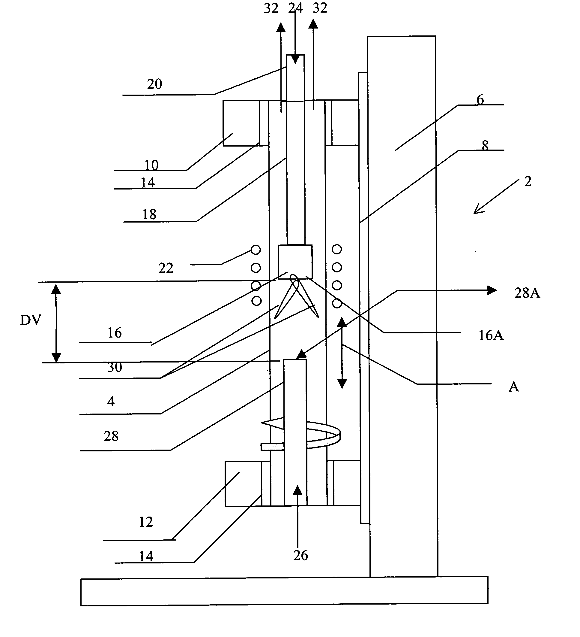
[0059] Applicants made a single mode preform, by using a deposition tube 4 having an inside diameter (ID) of 60 mm and an outside diameter (OD) of 64 mm. Applicants used a plasma gas feeder 18 with a diameter of 40 mm and a length of 80 mm. First, a cladding was deposited consisting of SiO2, GeO2, P2O5, and F with a thickness of 4 mm and then deposited a core with SiO2 and GeO2, for a step index profile, with a thickness of 1 mm. At a deposition rate of 8 g / min, the total deposition time was less than 5 hours. Then this tube was collapsed into a preform with an OD of 40 mm and a core diameter of 14 mm. To complete this single mode preform, more fused silica glass was deposited on the outside to build the final outer diameter to be 208 mm as a finished preform. From a meter long preform with this diameter, more than 2,700 km of single mode fiber could be produced.

[0060] Although the example preform was for making single mode step index preform, this method can make all types of pref...


PUM

PropertyMeasurementUnit
Pressureaaaaaaaaaa
Pressureaaaaaaaaaa
Lengthaaaaaaaaaa

Abstract

A plasma flame is generated in an interior volume of a tubular member to be a radially directed plasma flame, directed to an inside surface of the tubular member, and reagent chemicals are injected to form soot particles, and the soot particles are deposited on the inner surface by the plasma flame. The plasma flame is generated by establishing an electromagnetic field in a region in the tube interior and inserting a plasma gas feeder nozzle into the tube interior, with the nozzle structured to emit plasma gas in a manner forming the radially directed plasma flame.

Description

FIELD OF THE INVENTION [0001] The invention relates to the manufacture of optical fiber and, more particularly, to the deposition and sintering of materials using a plasma torch. DESCRIPTION OF BACKGROUND INFORMATION [0002] Optical fiber has been manufactured in commercial quantities since at least the early 1970s. One example of the known manufacturing methods is to first make a cylindrical preform, generally of a silica material, and then heat the preform to a viscous state and draw it into a fiber. The silica material making up the preform is typically mixed with selected chemicals to impart a desired cross sectional profile of optical qualities, particularly with respect to the index of refraction. [0003] One example process for making preforms is Outside Vapor Deposition (OV) such as described by, for example, U.S. Pat. No. 3,737,292 to Keck, and U.S. Pat. No. 3,932,162 to Blankenship. Another example known process for making preforms is Vapor Axial Deposition (VAD) such as des...

Claims


Application Information

Patent Timeline
IPC IPC(8): C03B37/018H05H1/30
CPCC03B37/0183H05H1/30C03B37/01884
Inventor GUSKOV, MICHAEL I.DANILOV, EVGUENIY B.VON SALDERN, JOHANN CHRISTOPHASLAMI, MOHDWU, DAU
Owner GUSKOV MICHAEL I
Why Eureka
Try Eureka