Scanning Range Sensor

a range sensor and sensor technology, applied in the field of scanning range sensors, can solve the problems of large outward-extending portions, limited device installation freedom, blind spots, etc., and achieve the effect of shortening the distance between the optical axis and shortening the distance from the sensor to the obj

Active Publication Date: 2005-02-03
HOKUYO AUTOMATIC CO +1
View PDF11 Cites 61 Cited by
  • Summary
  • Abstract
  • Description
  • Claims
  • Application Information

AI Technical Summary

Benefits of technology

[0013] An object of the present invention is to shorten the distance between the optical axis of the beam projected from a scanning range sensor toward an object and the optical axis of light reflected by the object into the sensor, thus to make it possible to prevent the sensor from having a blind spot even when the distance from the sensor to the object is short.

Problems solved by technology

However, there are some drawbacks to the configuration shown in FIG. 5.
Therefore, if a target object is positioned within close range, light reflected from the object does not enter the photodetector 56, resulting in the occurrence of a blind spot.
Secondly, the fact that the scanning and receiving optics are situated respectively above and below the motor renders the sensor as a unit elongate vertically.
This limits the degrees of freedom for installation in a device.
In particular, if the sensor is to be installed in a low-profile device, a drawback is that the outward-extending portions are large.
In addition, there are a few drawbacks to the configuration shown in FIG. 6.
If the photodetector 56 is of enhanced photosensitivity, the stray reflected light may generate noise that becomes added to image information.
Consequently, the photosensitivity cannot be heightened without compensating for it.

Method used


Image

  • Scanning Range Sensor
  • Scanning Range Sensor
  • Scanning Range Sensor

Examples


first embodiment

[0035] First Embodiment

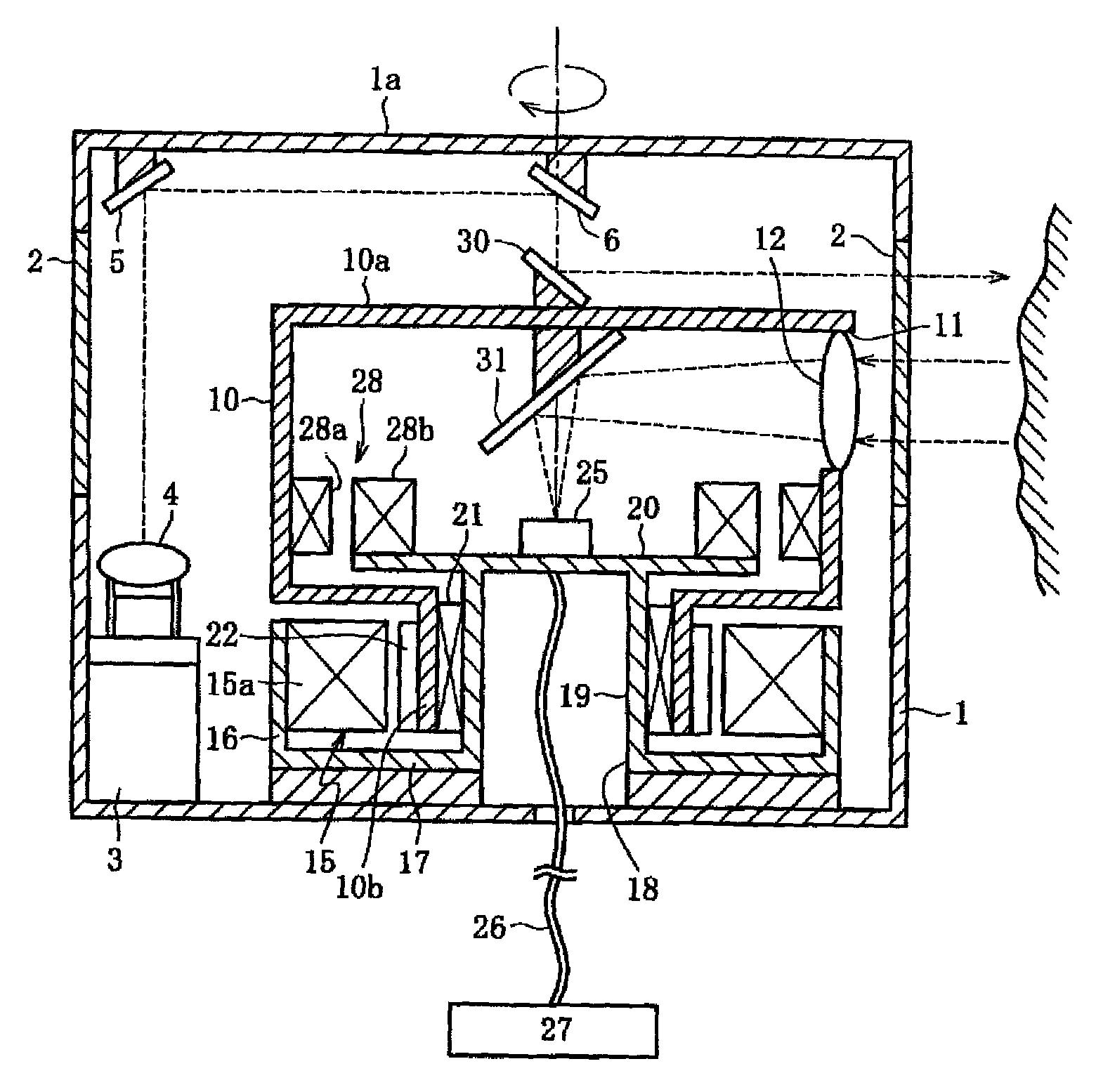
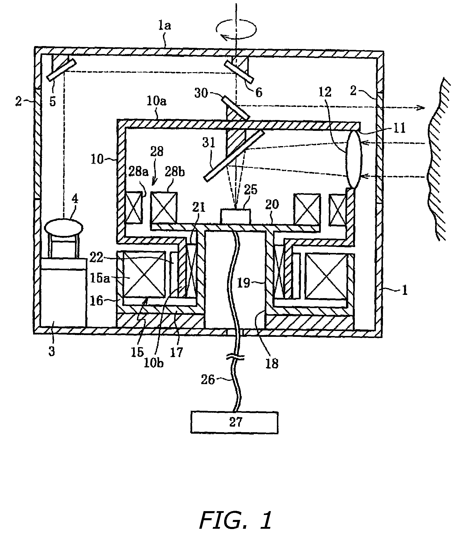
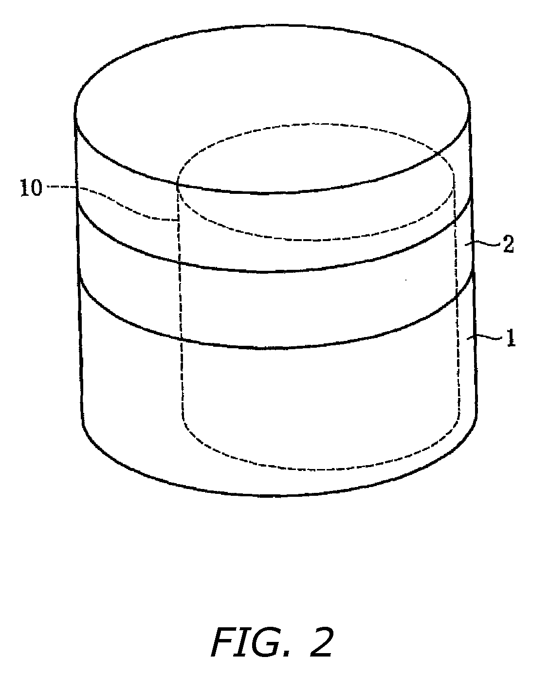
[0036] First, FIGS. 1-3 show a first example of the present invention. In this example, a vertically cylindrical outer cover 1 houses a main body of a scanning range sensor. When using the scanning range sensor of the present invention for a guarding robot or a cleaning robot, the outer cover 1 is placed on the top of the head portion of the robot. The outer cover 1 is made of an appropriate material such as a synthetic resin. As indicated in FIGS. 1 and 2, midway height-wise along the circumferential wall of the outer cover 1, a transparent window 2 that has a horizontally annular form and a uniform vertical width is formed slightly above center. This transparent window 2 may be made of a transparent, annularly seamless, band-shaped constituent separate from the main material of the outer cover 1 and set into position as the transparent window. Alternatively, the outer cover 1 itself may be formed integrally of a transparent material, and then a portion excep...

second embodiment

[0045] Second Embodiment

[0046] Next, a second embodiment of the present invention will be described with reference to FIG. 4. This example is a variation in which the light projector 3 is arranged on the disk portion 20 inside the cylindrical rotary member 10. Because a half-silvered mirror 35 is used, if a laser is used as a light source, the photosensitivity must be limited for safety by restricting the output power. On the other hand, however, a significant advantage to this configuration is that the vertical height of the scanning range sensor can be further decreased because it is possible to eliminate the mirrors 5 and 6 on the inner surface of the outer cover 1 shown in FIG. 1. In FIG. 4, the beam reflected upward by the half-silvered mirror 35 is incident upon the lower surface of the scanning mirror 36 through a tiny optical through-hole 37 in the center of the reflecting mirror 31, and a tiny optical through-hole 38 in the center of the top plate portion 10a of the cylindr...


PUM


Abstract

A scanning range sensor includes an outer cover having a transparent window that is horizontally annular, a vertical type cylindrical rotary member inside the outer cover, a light receiving window with an optical lens of the cylindrical rotary member, a light projector between the outer cover and the cylindrical rotary member, an optical system for leading light from the light projector along the direction of the rotational axis of the cylindrical rotary member by the mirrors on the inner surface of the cylindrical rotary member, a photodetector that within the interior of the cylindrical rotary member is fixed and arranged separately from the cylindrical rotary member so as to coincide with the rotational axis of the cylindrical rotary member and is connected to a distance computation circuit, and a reflecting mirror and scanning mirror along the rotational axis of the cylindrical rotary member.

Description

BACKGROUND OF INVENTION [0001] 1. Technical Field [0002] The present invention relates to so-called scanning range sensors, which use a rotating or vibrating mirror or an equivalent to scan an object with a light beam within a predetermined angle range, and which receive light reflected by the object [0003] 2. Description of the Related Art [0004] There are two different configurations, as shown respectively in FIGS. 5 and 6, known as a scanning range sensor that uses a rotating mirror for deflecting the axis of an optical beam over a full, 360-degree range of angles. Both configurations have a mirror whose optical axis coincides with the axis of a motor for rotating the mirror. [0005] The configuration shown in FIG. 5 uses a motor 52 having rotary shafts 51a and 51b that constitute a common shaft and extend upward and downward, respectively. A scanning mirror 53 and a reflecting mirror 54 are attached to respective shafts 51a and 51b so as to have identical phase. At numeral 55 in ...

Claims


Application Information

Patent Timeline
Patent Type & Authority Applications(United States)
IPC IPC(8): G01S17/06G01C15/00G01S7/481G01S17/42G01S17/931
CPCG01C15/002G01S7/4811G01S17/936G01S7/4817G01S17/42G01S7/4813G01S17/931
Inventor MORI, TOSHIHIROYAMASHITA, MAKOTO
Owner HOKUYO AUTOMATIC CO
Why Eureka
Try Eureka