Self diagnostic and repair in matrix display panel

a matrix display panel and self-diagnosis technology, applied in the field of matrix display panel self-diagnosis and repair, can solve the problems of reducing the production yield of the panel substantially, increasing the chances of production defects, and the cost of the display system, so as to achieve the effect of improving the effective yield

Inactive Publication Date: 2005-02-03
LAMBERT NICHOLAAS
View PDF11 Cites 18 Cited by
  • Summary
  • Abstract
  • Description
  • Claims
  • Application Information

AI Technical Summary

Benefits of technology

[0009] The column drive circuitry for a matrix display consists mostly of a large number of identical circuits, one for every column. By providing at least one spare column driver and a control circuit within each block of drivers, the system can automatically detect and identify faulty column drivers, which are then functionally replaced with a spare driver. Thus, with the addition of a small amount of extra circuitry, the effective yield can be improved.

Problems solved by technology

The integration of column drive circuits on a silicon display panel potentially reduces the cost of display systems, but may also reduce the panel fabrication yield substantially.
However, a large active circuit area may increase the chances for production defects substantially.
In addition, some pixel defects are generally acceptable as long as they result in dark point defects in the image.
Defects in the data conversion and driver circuitry, however, typically cause one or more rows or columns to fail, a result that is unacceptable.
Therefore, when the dense active circuit area for data conversion and drivers increases, the production yield may be adversely affected, which raises the cost.
This takes valuable time and the mechanics of the fuse programming may be difficult to implement.
Therefore, standard laser activated fuse programming is difficult to perform.
Another reason is that the blowing of a fuse may actually create damage to the die surface that can easily compromise the tight tolerances on the narrow gap of liquid crystal cell on top of it.

Method used


Image

  • Self diagnostic and repair in matrix display panel
  • Self diagnostic and repair in matrix display panel
  • Self diagnostic and repair in matrix display panel

Examples


example 1

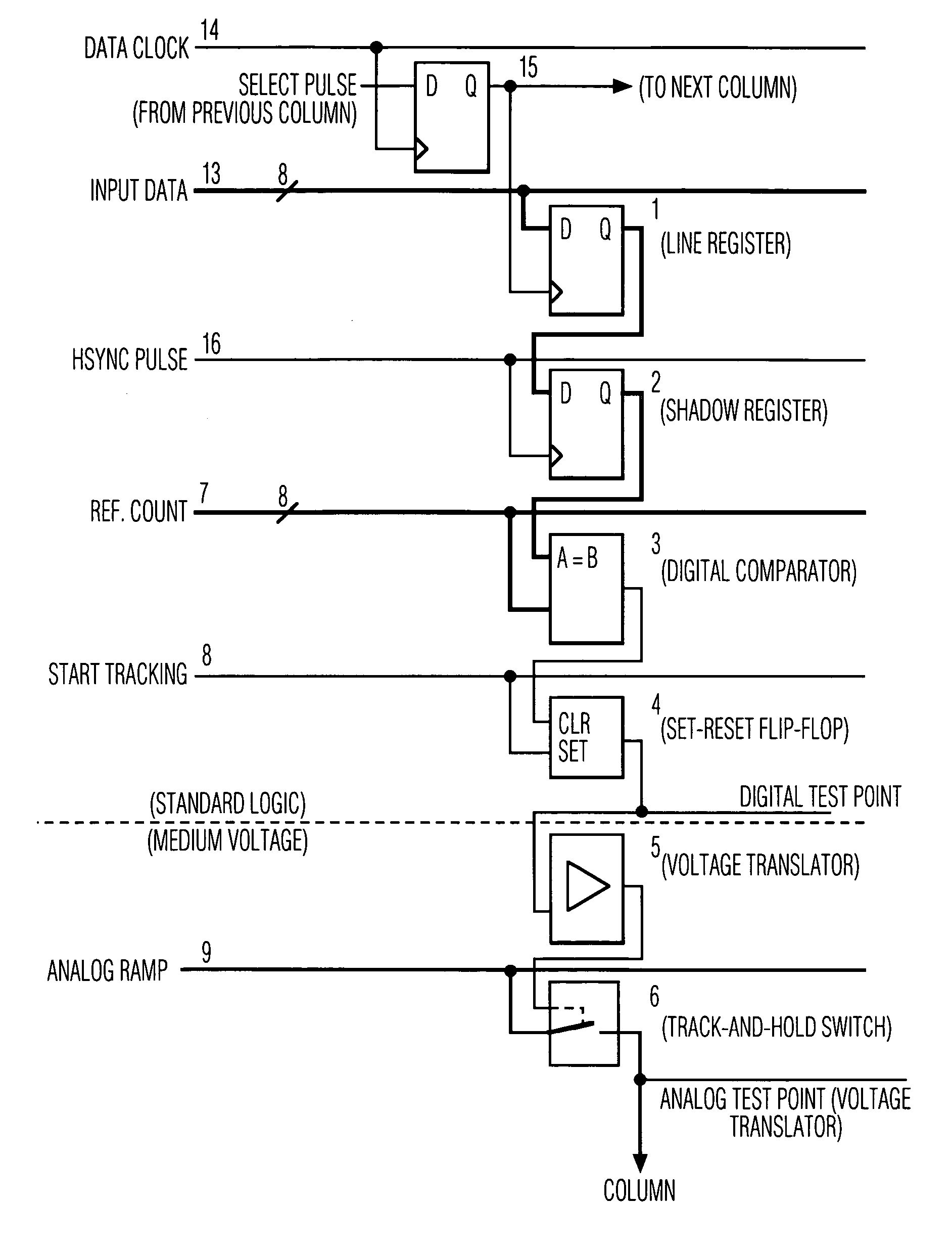
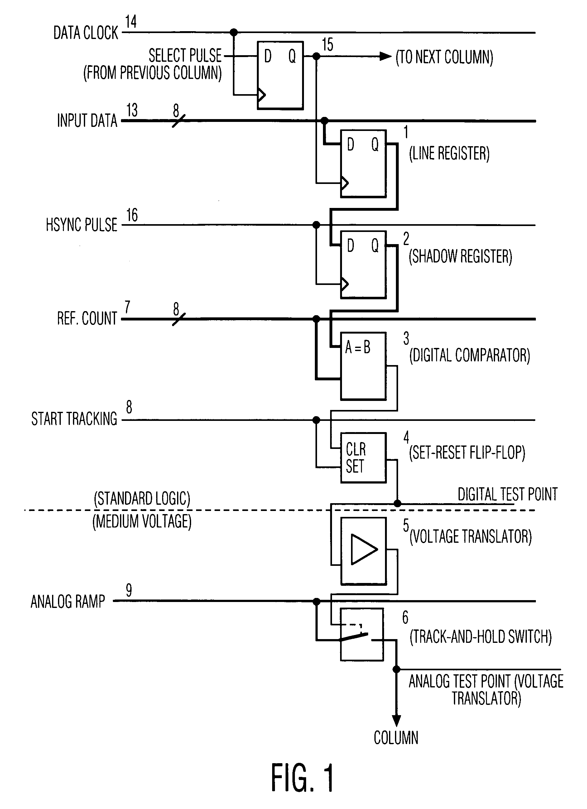
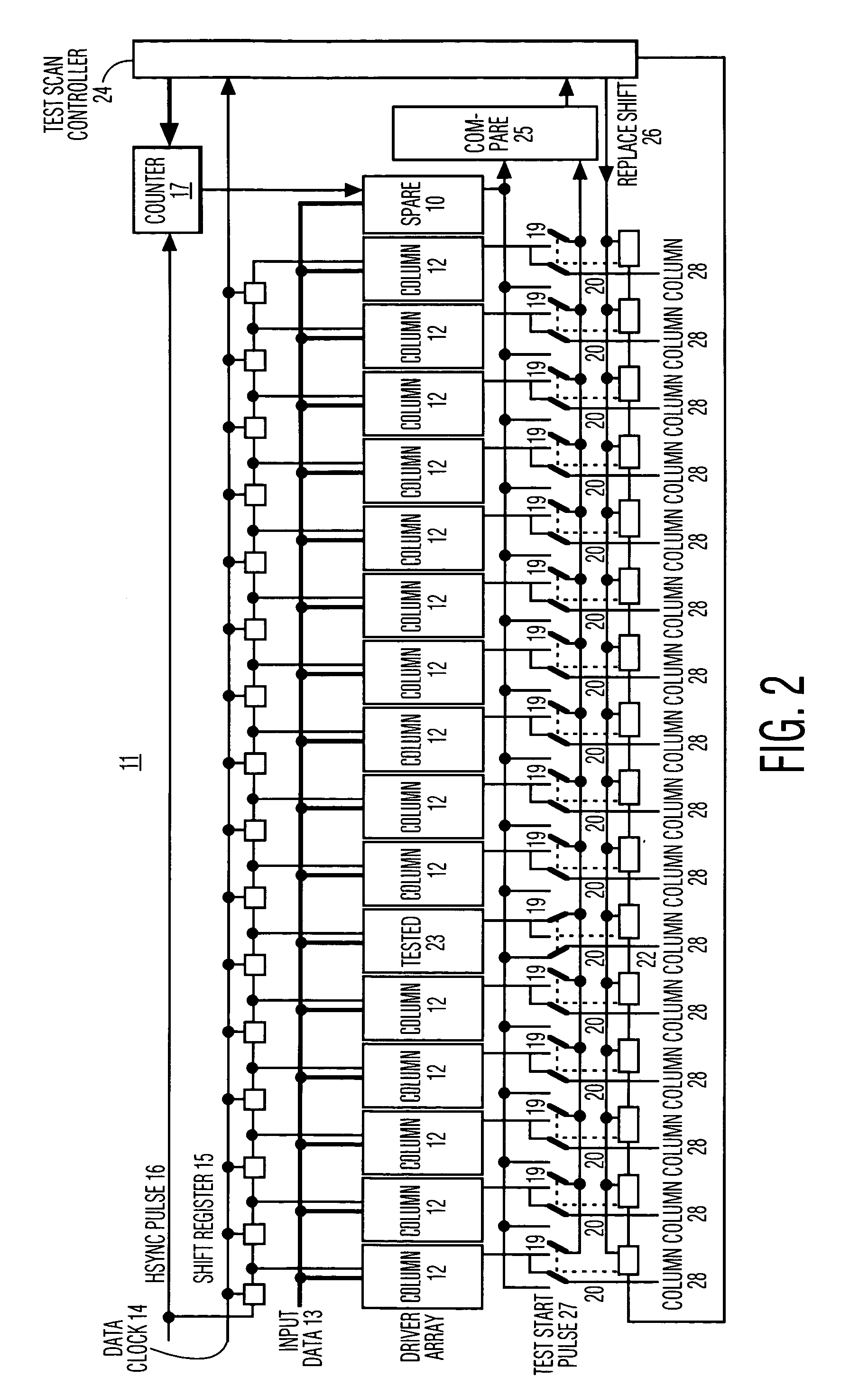
[0040] According to a first exemplary embodiment of the invention, a spare column driver circuit 10 is provided for a block of column drivers 11, as shown in FIG. 2. Each column driver circuit 12 is relatively standard, having a data line register 1, a shadow register 2, digital comparator 3 and set-reset flip-flop 4, a voltage translator 5 and track-and-hold switch 6 as shown in FIG. 1. An input data bus 13 delivers the gray scale input data signal to each column driver circuit 12. The input data is stored in the line register 1 during the remainder of the line period. At the end of the line period, when all columns have been loaded with the proper gray scale input data, the data are transferred to the shadow register 2, controlled by global horizontal synchronization (Hsync) pulse 16. When the data from the shadow register 2 is equal to the value of global reference count 7, the digital comparator 3 clears the set-reset flip-flop 4, signifying the “end-of-tracking” or “hold” condi...

example 2

[0045]FIG. 3 shows a second exemplary embodiment of the invention. According to the second embodiment, a spare column driver circuit 30 is provided within a block of column drivers 31. The column drivers 32 are similar to the column driver circuits 12 described in Example 1, and shown in FIG. 1.

[0046] A data bus 34 delivers the data control signal to each column driver 32. A data clock 35, horizontal synchronization pulse 36, and shift register 37 generate the necessary address signal for each column driver circuit 32 to selectively read the appropriate data signal. The horizontal synchronization pulse 36 also provides an input to test scan controller 38. The output generated by each column driver 32 is (n:1) multiplexed onto a test line 39 by multiplexer circuits 40, and further (2:1) multiplexed by multiplexer circuits 41 with the output of an adjacent column driver 32 to a respective column drive line 42 of the column drive 32. A relatively simple comparator 47 is provided for e...


PUM


Abstract

A matrix access system having a plurality of columns, comprising a plurality of circuits each being adapted for selectively accessing one of said columns; an interface, communicating data with said plurality of circuits; at least one redundant circuit, adapted for selectively accessing each of said columns and communicating data with said interface; a test circuit, for comparing data communicated by a respective one of said circuits and said redundant circuit; and means for selectively logically replacing a respective circuit with said redundant circuit.

Description

FIELD OF THE INVENTION [0001] The present invention relates to the field of self-repair of matrix accessed integrated electronics systems, and more particularly to matrix display panels with integrated drivers capable of self-diagnostic and repair through the use of redundant driver circuitry. BACKGROUND OF THE INVENTION [0002] The integration of column drive circuits on a silicon display panel potentially reduces the cost of display systems, but may also reduce the panel fabrication yield substantially. This is the obvious result of the inclusion of sensitive small geometry active circuit elements on the substrate. [0003] One of the advantages of building a reflective active matrix projection display with liquid crystal on silicon is that the drivers can be integrated with the active matrix itself. This should improve performance and reliability, and lower the total system cost. By integrating the digital to analog conversion on the display panel, a purely digital interface can be ...

Claims


Application Information

Patent Timeline
Patent Type & Authority Applications(United States)
IPC IPC(8): H04N7/30G06T9/00H03M7/30H04N1/41
CPCG06T9/007
Inventor LAMBERT, NICHOLAAS
Owner LAMBERT NICHOLAAS
Why Eureka
Try Eureka