Capped microsensor

a microsensor and cap technology, applied in the direction of fluid tightness measurement, simultaneous indication of multiple variables, instruments, etc., can solve the problem of not being able to measure pressure in small cavities without problems, and achieve the effect of cost-effective manufacture and simple manufacturing

Inactive Publication Date: 2005-02-10
ROBERT BOSCH GMBH
View PDF3 Cites 13 Cited by
  • Summary
  • Abstract
  • Description
  • Claims
  • Application Information

AI Technical Summary

Benefits of technology

[0012] In a second preferred embodiment according to the present invention, the pressure in the cavity is detected using the 3 ω method, an expanded thermal conduction model preferably being used for the 3 ω method—as specified above—which takes multilayer systems having additional cover layers into consideration, the gaseous medium surrounding the structure being treated as a cover layer. In this way, the effect that thermal conductivity and heat capacity of the gaseous medium, preferably air, are pressure-dependent is exploited. The structure described, having resistance bridges connected thereto, prefer

Problems solved by technology

The measurement of pressures in small ca

Method used


Image

  • Capped microsensor
  • Capped microsensor
  • Capped microsensor

Examples


Embodiment Construction

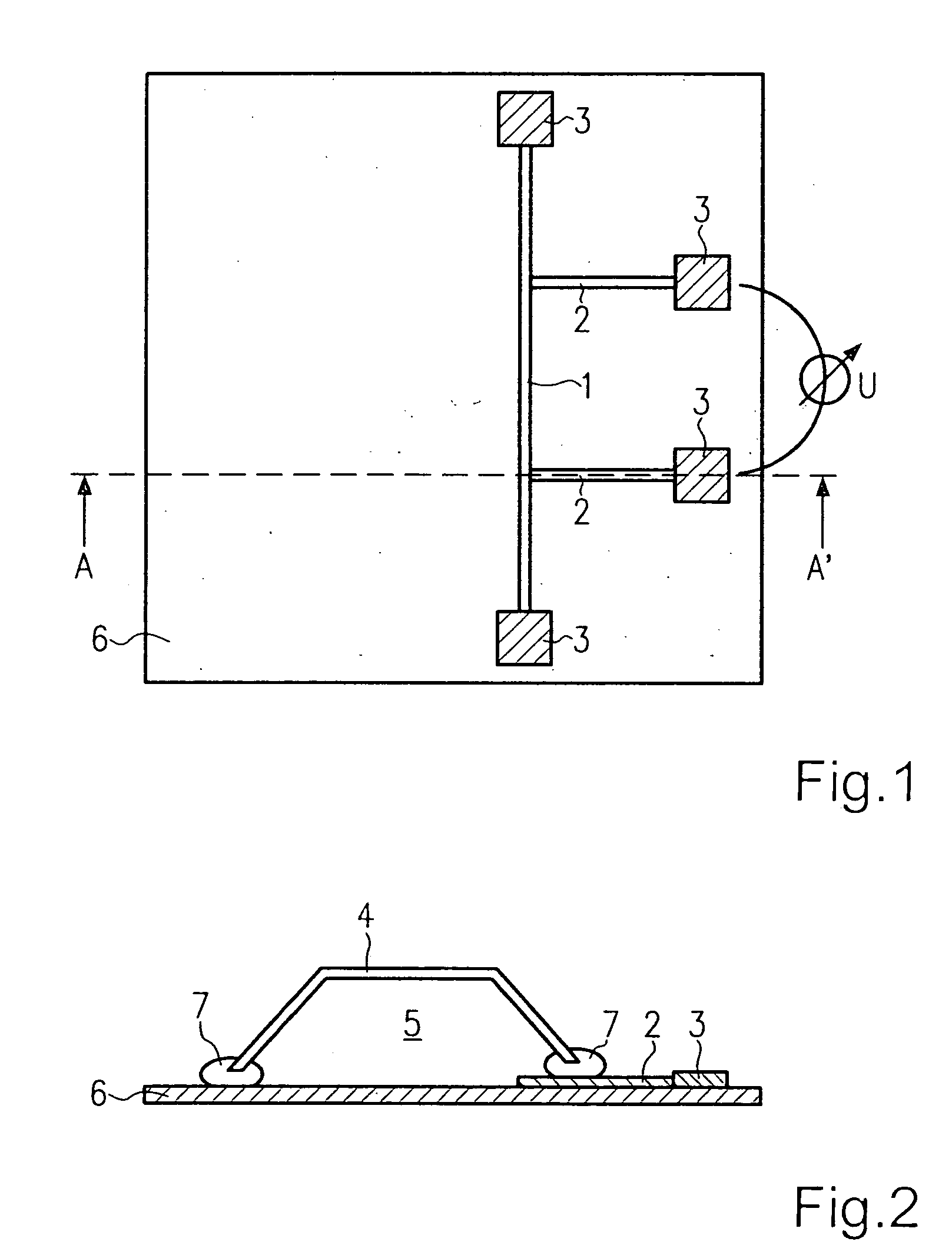
[0019] In the following, a capped microsensor according to the present invention is described with reference to FIGS. 1 and 2. FIG. 1 shows a microsensor according to the present invention which is not yet capped, the elements of the actual microsensor not necessary for implementing the present invention not being shown.

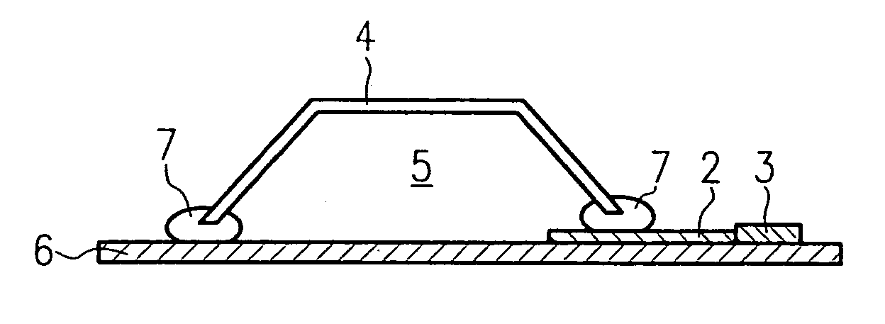
[0020] A current conductor 1, which has two voltage taps 2, is applied to a substrate 6 of the microsensor. Contact pads 3 are provided at the ends of current conductor 1 and at the ends of both voltage taps 2. The printed conductors forming current conductor 1, both voltage taps 2, and contact pads 3 may be manufactured using the uppermost metal layer of the microsensor, for example.

[0021] Reference is made to DE 101 23 290 A1, which is included by reference, for the selection of specific materials and in regard to a special configuration of current conductor 1 and voltage taps 2.

[0022] According to the present invention, current conductor 1 and voltage taps 2 li...


PUM


Abstract

A capped microsensor is described. It is suggested that a current conductor, positioned in the cavity and having at least two voltage taps, be provided, this configuration being used for seal testing, e.g., during quality control, by detecting at least one thermodynamic variable of a gaseous medium present inside the cavity via this configuration.

Description

FIELD OF THE INVENTION [0001] The present invention is directed to a capped microsensor and a method for seal testing of a capped microsensor. BACKGROUND INFORMATION [0002] The measurement of pressures in small cavities is not possible without problems. However, it is necessary in order to determine whether the capping of microsensors is sealed or whether leaks have arisen, for example. Such a seal test is important for all hermetically capped microsensors, such as yaw rate sensors, acceleration sensors, HF-MEMS, etc. [0003] An extremely miniaturized pressure sensor, whose sensor principle is based on a pressure-dependent heat loss of a microbridge, a gap having to exist between the microbridge and a substrate over which the microbridge is formed, is known from “The NanoPirani—Presumably the World's Smallest Pressure Sensor”, Reyntjens, S., De Bruyker, D., Puers, R., TRANSDUCERS' 01, EUROSENSORS XV, 11th International Conference on Solid-State Sensors and Actuators, Digest of Techni...

Claims


Application Information

Patent Timeline
IPC IPC(8): H01L23/02B81B7/00G01M3/00
CPCB81B2201/0264G01M3/002B81C99/0045
Inventor SCHATZ, FRANKRAUDZIS, CARSTENREIMANN, MATHIAS
Owner ROBERT BOSCH GMBH
Why Eureka
Try Eureka