Hollow cathode sputtering apparatus and related method

a hollow cathode sputtering and film-deposited technology, applied in vacuum evaporation coatings, electrolysis components, coatings, etc., can solve the problems of unbalanced magnetron sputtering, low deposition rate, undesirable chemical vapor deposition

Inactive Publication Date: 2005-02-10
NEW MILLENNIUM SOLAR EQUIP CORP
View PDF6 Cites 26 Cited by
  • Summary
  • Abstract
  • Description
  • Claims
  • Application Information

AI Technical Summary

Benefits of technology

[0009] The present invention overcomes the problems of the prior art by providing in one embodiment an improved method for sputter coating a substrate. The method of the invention is a hollow cathode sputtering process which comprises providing a channel for gas to flow through, the channel defined by a channel defining surface wherein one or more portions of the channel-defining surface includes at least one target material. Gas is flowed t...

Problems solved by technology

Chemical vapor deposition can be undesirable because of contamination of the deposited films.
It is particularly useful for depositing both insulating and oxide films, but deposition rates tend to be low.
These refinements include unbalanced magnetron spu...

Method used


Image

  • Hollow cathode sputtering apparatus and related method
  • Hollow cathode sputtering apparatus and related method
  • Hollow cathode sputtering apparatus and related method

Examples


example 1

[0044] Copper films were deposited in accordance to the method of the present invention at a power of 1000 W, a pressure of 400 mTorr, and an argon flow rate of 4 slm. The resistivities for a series of copper films for varying substrate conditions is provided in Table 1.

TABLE 1Resistivity of copper oxide filmsdepositionfilm resistivityconditions(microhm cm)unheated substrate8.5bias −30 V,4.2unheated substratebias −15 V,3.9substrate 70° C.substrate heated to3.370° C.bias −30 V,2.4substrate 70° C.

example 2

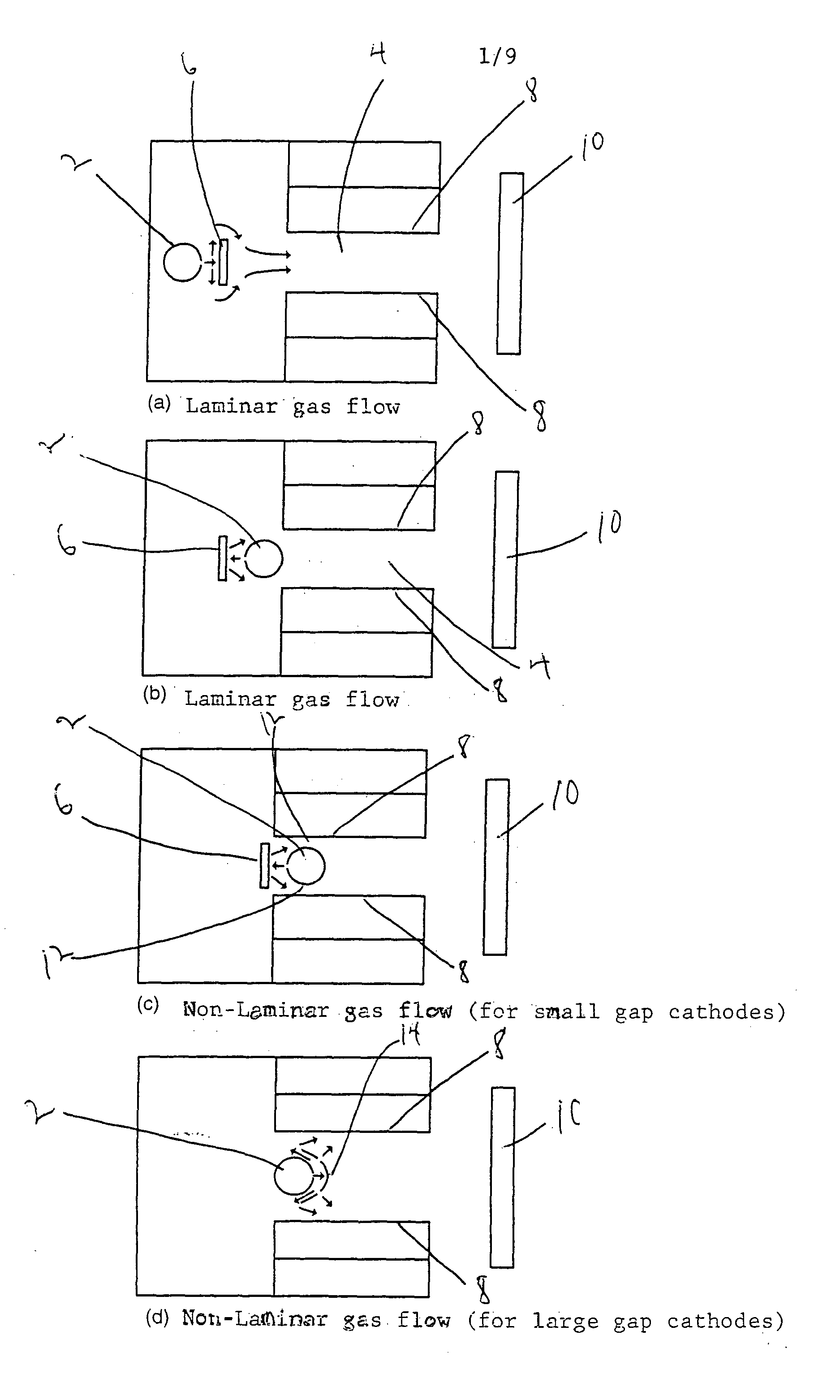
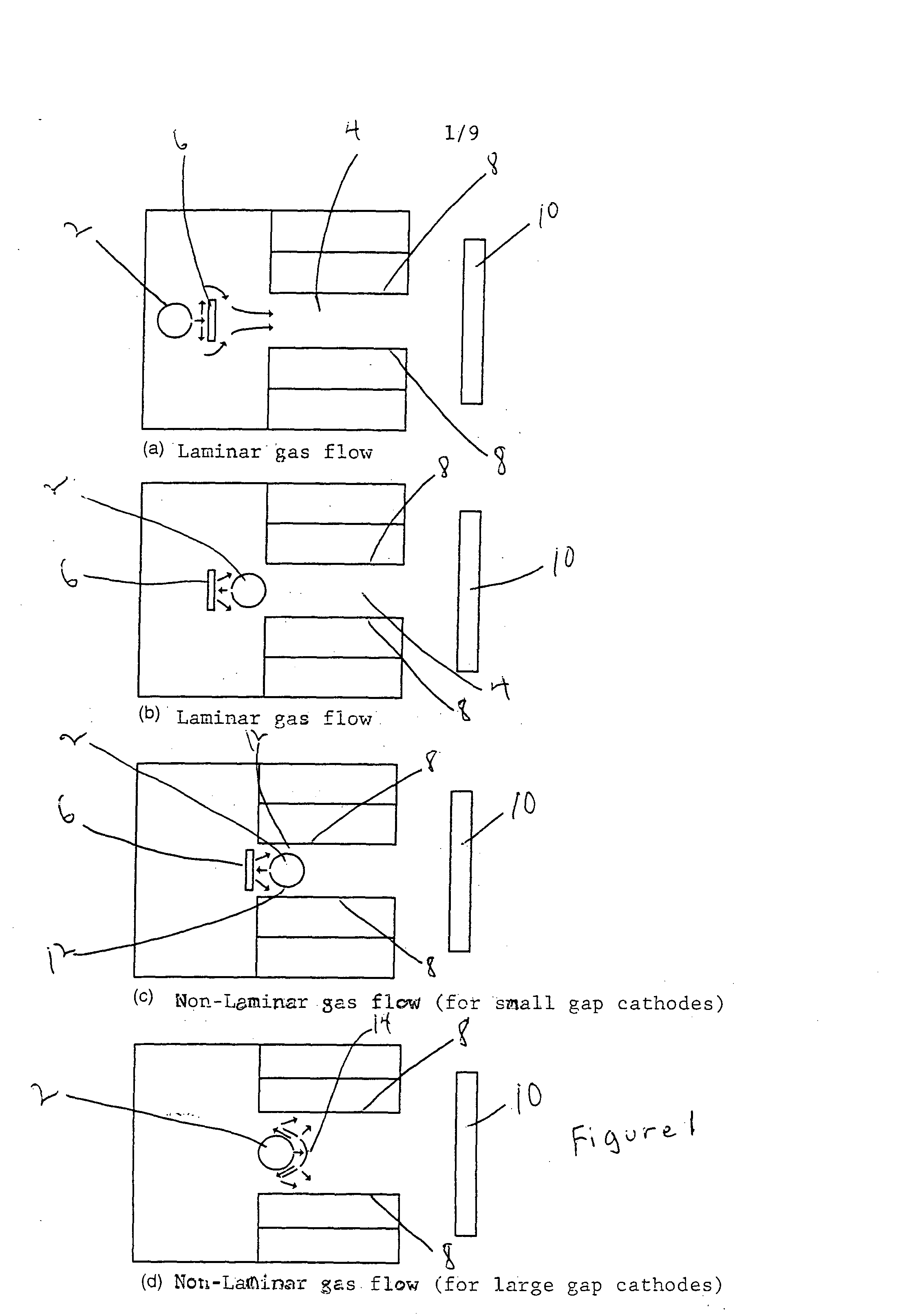
[0045] Aluminum oxide films were deposited by the method of the invention with a power of 300 W, a pressure of 250 mTorr, and an argon flow rate of 4 slm. The argon was injected using the arrangement of FIG. 1C. FIG. 6 is a plot of the deposition rate as a function of oxygen flow rate. The reactive gas O2 is used here for two different cases: O2 goes through the channel and O2 is outside the channel. The deposition rate was measured by crystal monitor.

example 3

[0046] Zinc oxide films were deposited by the method of the invention with power of 150 W, a pressure of 500 mTorr, and an oxygen flow rate of 150 sccm. FIG. 7 is a plot of zinc oxide growth rate as a function of the argon flow rate for deposition in a hollow cathode reactor where the argon is introduced non-turbulently and turbulently. In the case of turbulent flow, the film growth rate is observed to be significantly greater for all argon flow rates.


PUM

PropertyMeasurementUnit
Temperatureaaaaaaaaaa
Lengthaaaaaaaaaa
Lengthaaaaaaaaaa

Abstract

The present invention provides an improved hollow cathode method for sputter coating a substrate. The method of the invention comprises providing a channel for gas to flow through, the channel defined by a channel defining surface wherein one or more portions of the channel-defining surface include at least one target material. Gas is flowed through the channel wherein at least a portion of the gas is a non-laminarly flowing gas. While the gas is flowing through the channel a plasma is generated causing target material to be sputtered off the channel-defining surface to form a gaseous mixture containing target atoms that is transported to the substrate. In an important application of the present invention, a method for forming oxide films and in particular zinc oxide films is provided.

Description

BACKGROUND OF THE INVENTION [0001] 1. Field of the Invention [0002] The present invention is related to methods and related apparatus for depositing films on a substrate by hollow cathode sputtering. More particularly, the present invention relates to methods and apparatus for depositing oxide and other films by hollow cathode sputtering. [0003] 2. Background Art [0004] Numerous methods are known for depositing thin films on a substrate. Such methods include, for example, sputtering, vacuum evaporation, chemical vapor deposition, and the like. Typical substrates that are coated with thin films are glass, ceramics, and silicon wafers. Vacuum evaporation is a low pressure deposition technique in which a material is vaporized by heating. Vacuum evaporation is a line of sight deposition technique in which the vaporized material is then radiated out in straight lines from the source. Chemical vapor deposition is a thin film deposition technique in which a reactive gaseous mixture is heat...

Claims


Application Information

Patent Timeline
IPC IPC(8): C23C14/08C23C14/14C23C14/32C23C14/34H01J37/34
CPCC23C14/08C23C14/081C23C14/14C23C14/228H01J37/342C23C14/345H01J37/32449H01J37/34C23C14/34
Inventor DELAHOY, ALAN E.GUO, SHEYU
Owner NEW MILLENNIUM SOLAR EQUIP CORP
Why Eureka
Try Eureka