

Liquid crystal display device and electronic apparatus
a liquid crystal display and electronic equipment technology, applied in the field of liquid crystal display devices, can solve the problems of degrading audio signal quality, giving an uncomfortable feeling to a listener, and noise on the output sound, so as to improve the s/n ratio, improve the amplitude, and improve the effect of output signal amplitud
- Summary
- Abstract
- Description
- Claims
- Application Information
AI Technical Summary
Benefits of technology
Problems solved by technology
Method used
Image

Examples
embodiment 1
[0094] [Embodiment 1]
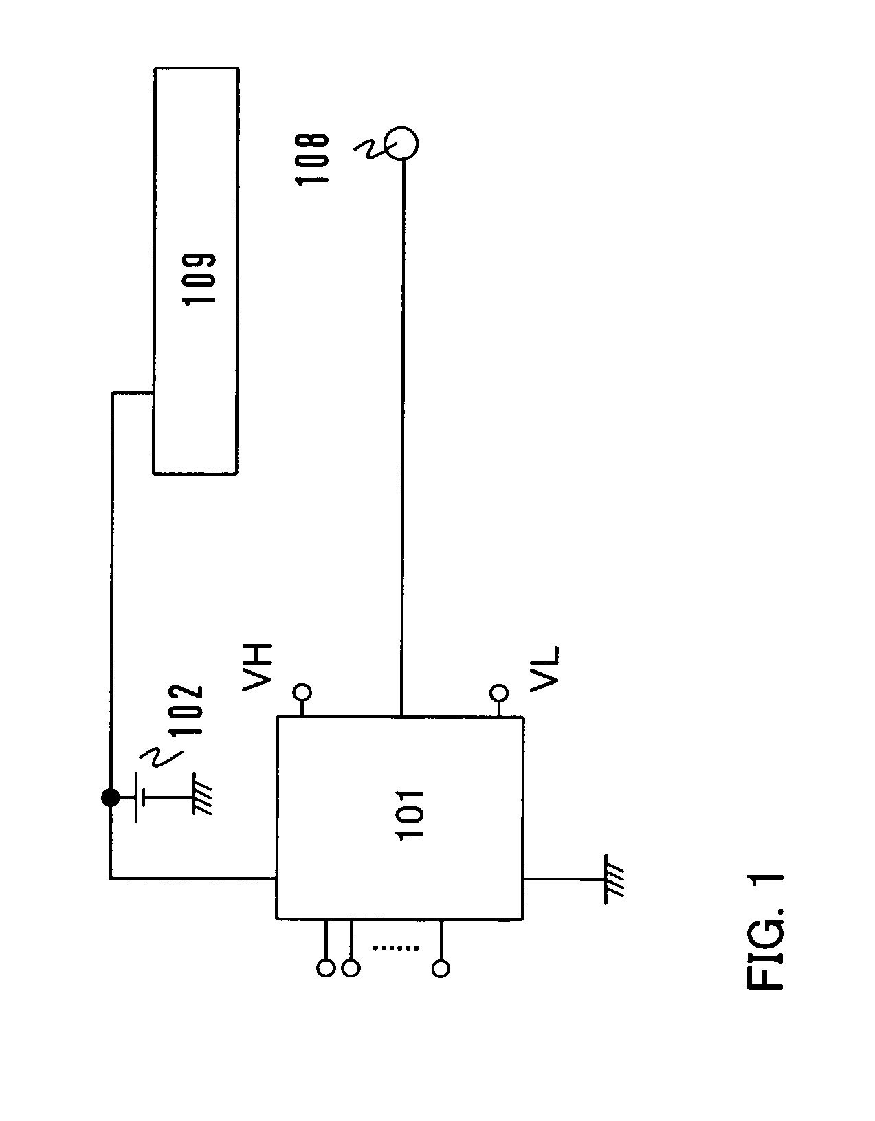
[0095]FIG. 22 is a diagram showing Embodiment 1 of the invention. As shown in FIG. 22, a circuit of this embodiment mode includes a D / A converter circuit 2201, a power supply 2202 for the D / A converter circuit 2201, an attenuator circuit 2204, an amplifier circuit 2206, an analog audio signal input terminal 2207, a D / A selection switch 2205, a speaker connecting portion 2208 and a signal line driver circuit 2209. Description is given below on the assumption that the signal level of the analog audio signal input terminal 2207 is at 283 mVpp while the signal level of the speaker connecting portion 2208 is at 10 Vpp as in the conventional circuit.
[0096] In this embodiment, the D / A converter circuit 2201 is connected to the same power supply voltage as the signal line driver circuit 2209 to obtain a high level voltage. For example, when the power supply 2202 for the D / A converter circuit 2201 is set at 16 V, the D / A converter circuit 2201 can obtain an output volta...
embodiment 2
[0101] [Embodiment 2]
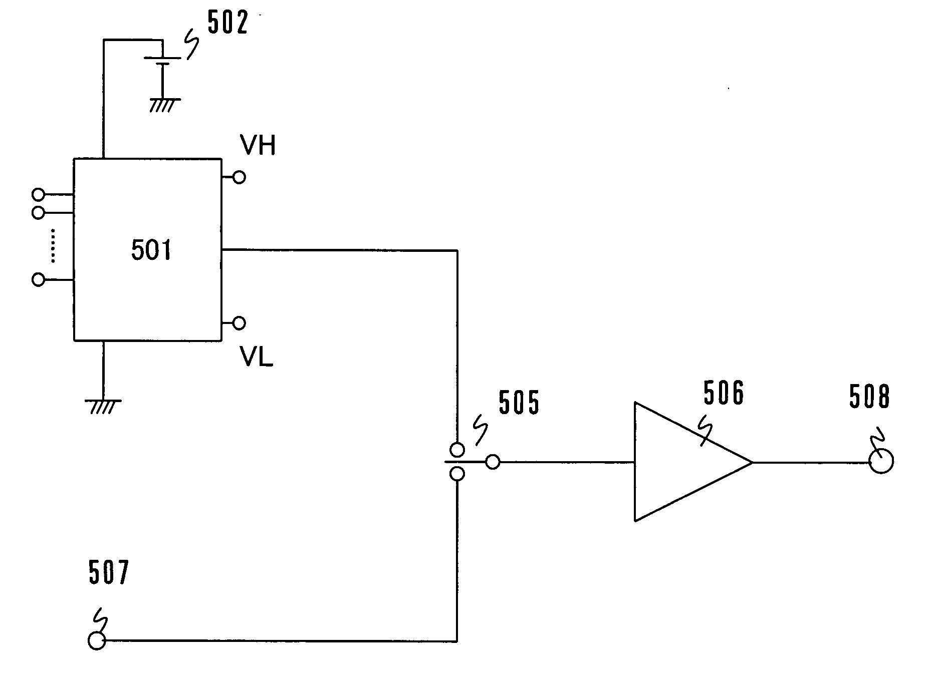
[0102]FIG. 7 is a diagram showing Embodiment 2 of the invention. As shown in FIG. 7, the circuit of this embodiment mode includes a D / A converter circuit 701, a power supply 702 for the D / A converter circuit 701, a first amplifier circuit 703, a second amplifier circuit 706, an analog audio signal input terminal 707, a D / A selection switch 705, a speaker connecting portion 708 and a signal line driver circuit 709. Description is given below on the assumption that the signal level of the analog audio signal input terminal 707 is at 283 mVpp while the signal level of the speaker connecting portion 708 is at 10 Vpp as in the conventional circuit.
[0103] In this embodiment, the D / A converter circuit 701 is connected to the same power supply voltage as the signal line driver circuit 709 to obtain a high level voltage. For example, when the power supply 702 for the D / A converter circuit 701 is set at 16 V, the D / A converter circuit 701 can obtain an output voltage hav...
embodiment 3
[0108] [Embodiment 3]
[0109]FIG. 8 is a diagram showing an embodiment of the invention. As shown in FIG. 8, the circuit of this embodiment mode includes a D / A converter circuit 801, a power supply 802 for the D / A converter circuit 801, an attenuator circuit 804, a first amplifier circuit 803, a second amplifier circuit 806, an analog audio signal input terminal 807, a D / A selection switch (switch for selecting a digital input or an analog input) 806, a speaker connecting portion 808, and a signal line driver circuit 809. Description is given below on the assumption that the signal level of the analog audio signal input terminal 807 is at 283 mVpp while the signal level of the speaker connecting portion 808 is at 10 Vpp as in the conventional circuit.
[0110] In this embodiment, the D / A converter circuit 801 is connected to the same power supply voltage as the signal line driver circuit 809 to obtain a high level voltage. For example, when the power supply 802 for the D / A converter cir...
PUM
 Abstract
Description
Claims
Application Information