Displacement gauge and displacement measuring method

Inactive Publication Date: 2005-02-10
KEYENCE
View PDF12 Cites 14 Cited by
  • Summary
  • Abstract
  • Description
  • Claims
  • Application Information

AI Technical Summary

Benefits of technology

[0022] With this constitution, the displacement measurement precision or measurement time may be adequately changed according to a user's desire. For example, the scan ste

Problems solved by technology

However, this displacement gauge had a problem that the spot size of light projected onto the measurement subject is so small as to make the measurement impossible depending on the surface conditions of the measurement subject.
For example, when there is an area where light is not normally reflected due to presence of a concave portion or hole on the surface of the measurement subject, the light projected from the

Method used


Image

  • Displacement gauge and displacement measuring method
  • Displacement gauge and displacement measuring method
  • Displacement gauge and displacement measuring method

Examples


embodiment 1

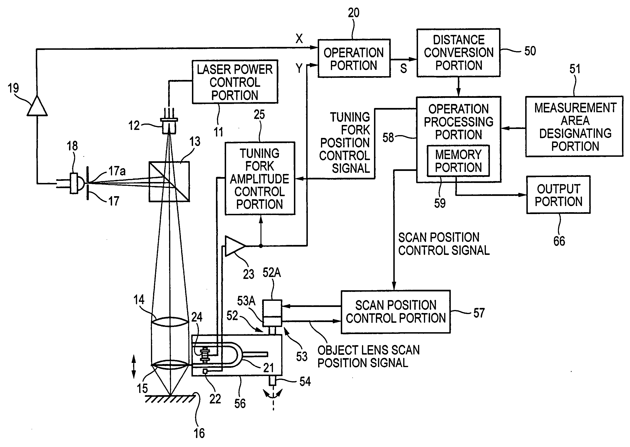
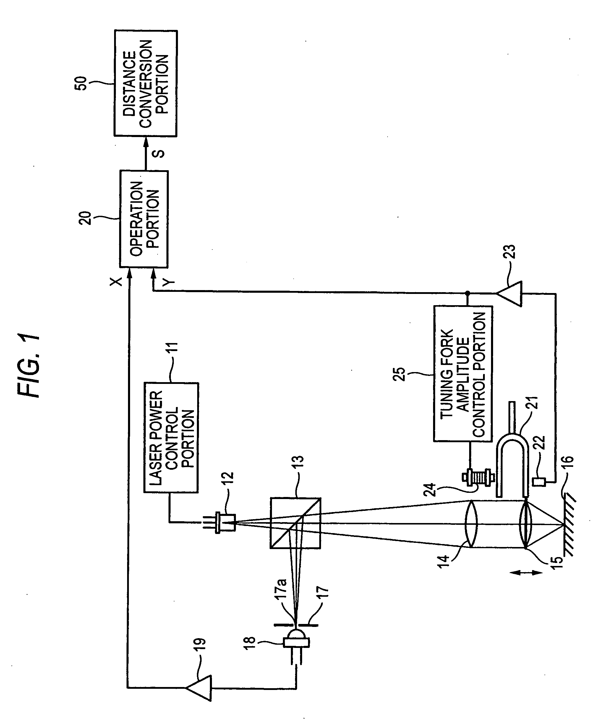
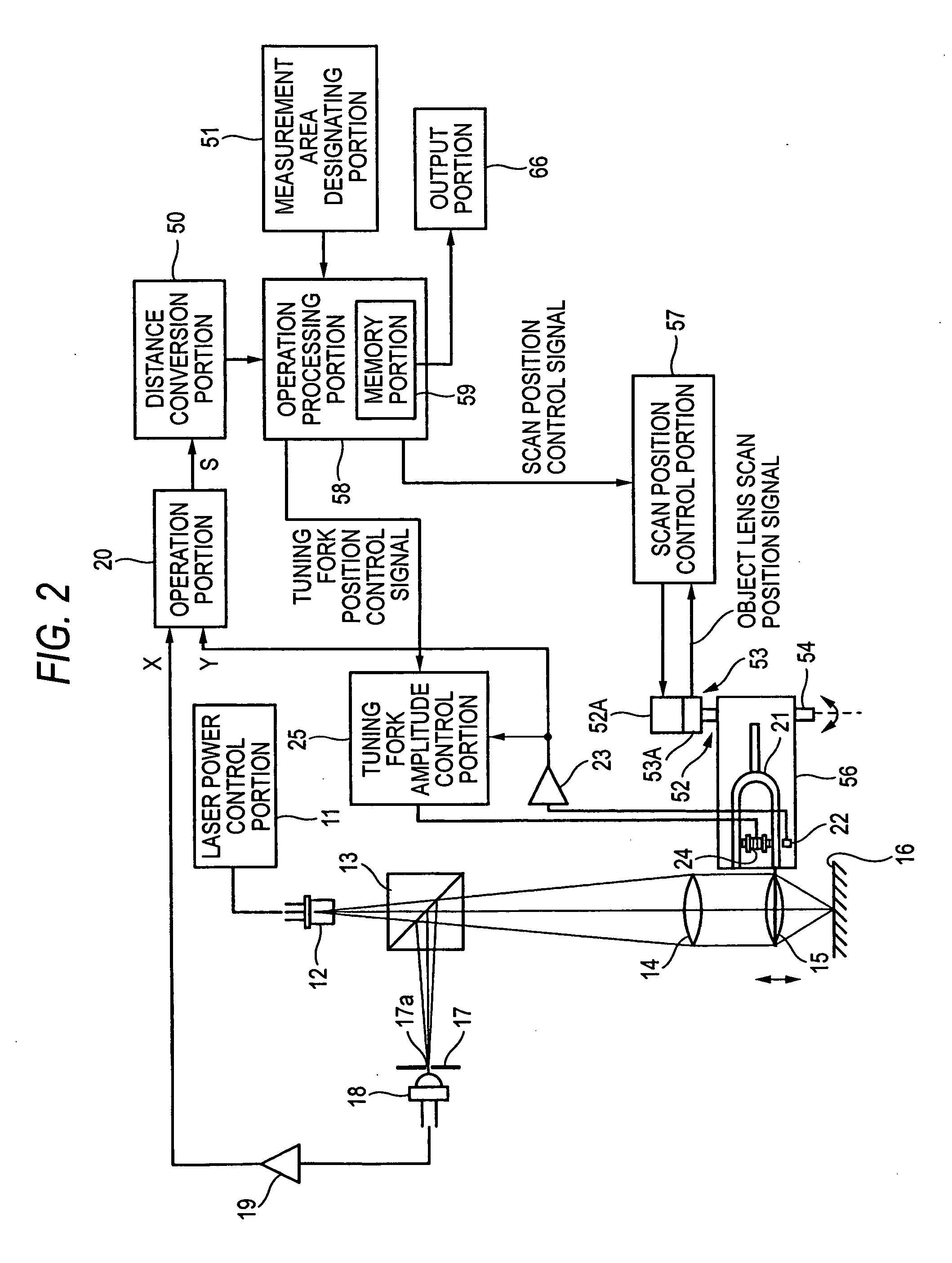
[0050]FIG. 2 is a block diagram of a displacement gauge according to an embodiment 1 of the invention. The displacement gauge as shown in FIG. 2 comprises a laser diode 12 as a light emitting portion, a collimator lens 14 for converting light emitted from the laser diode 12 into parallel light, an objective lens 15, a tuning fork 21 holding the objective lens 15, a solenoid 24 that is an exciting portion for oscillating the tuning fork 21 in the optical axis direction, and a tuning fork amplitude detecting portion 22 that is a position detector for detecting the position of the tuning fork 21 oscillated by the solenoid 24. Also, this displacement gauge has a pinhole 17a in a light diaphragm portion 17, through which the reflected light from the measurement subject 16 passes. Moreover, a photo-diode 18 is provided as a light receiving portion for receiving light through the pinhole 17a in the light diaphragm portion 17.

[0051] A light emitted from the laser diode 12 driven by the las...

embodiment 2

[0086] Though the servo motor 52A is employed as the objective lens scanning portion 52 in the constitution as shown in FIG. 2, the objective lens scanning portion is not limited thereto. FIG. 11 shows the displacement gauge according to another embodiment of the invention. The displacement gauge as shown in FIG. 11 has the almost same constitution as that of FIG. 2, except that the objective lens scanning portion 52 is a rotating mechanism with a voice coil 52B and a voice coil magnet 52C, and the objective lens movement detecting portion 53 includes a Hall element 53B and a Hall element magnet 53C.

[0087] The voice coil magnet 52C is fixed in an inner face of an opening portion in a rotational axis holding portion 55 holding a rotational axis 54 and fixed in a rest state, with the opening portion 60 like U-character in cross section. On the other hand, the voice coil 52B that juts out on the upper face of the tuning fork holder 56 is inserted into the opening portion 60, and fixed...

embodiment 3

[0092] In an embodiment 3, the displacement gauge further comprises an image pickup monitor 63 as shown in FIG. 14. The displacement gauge as shown in FIG. 14 comprises, in addition to the almost same constitution of FIG. 2, a second half mirror constituting a second beam splitter 64 provided on the optical path of the light emitting portion, an image sensor as a CCD camera as an image pickup light receiving portion 65 provided on the optical path of reflected light from the second half mirror, and an image pickup monitor 63 connected to the CCD camera. The image pickup camera 63 displays the measurement subject 16, based on a light reception signal detected by the CCD camera. The image pickup monitor 63 does not continuously display the measurement subject at any time while the objective lens 15 is moved, but picks up the image only at a specific timing to display a clear image in focus. The timing of picking up the image to be displayed on the image pickup monitor 63 takes place w...


PUM


Abstract

A displacement gauge comprises an objective lens 15 that projects light onto a measurement subject 16, an exciting portion that vibrates the objective lens 15 at a preset amplitude along an optical axis direction of light passing through the objective lens 15, a position detector for detecting the position of the objective lens 15, an objective lens scan portion 52 for scanning the objective lens 15 along a plane orthogonal to the optical axis direction, an objective lens movement detecting portion 53 for detecting the moved position of the objective lens 15, an operation processing portion 58 for calculating a distribution of displacement amount within a measuring area, based on the positional information of the objective lens 15 within the measuring area detected by the objective lens movement detecting portion 53, and the displacement amounts measured at plural measuring points, and an output portion 66 for outputting the result of calculation by the operation processing portion 58.

Description

DETAILED DESCRIPTION OF THE INVENTION [0001] 1. Technical Field to Which the Invention Belongs [0002] The present invention relates to a displacement gauge and a method for measuring a displacement on the surface of a measurement subject such as metal, resin, glass, ceramic or paper by projecting a light onto the surface of the measurement subject, as well as a thickness meter for measuring the thickness of the measurement subject based on the same measurement principle. [0003] 2. Related Art [0004] As an instrument for measuring a displacement on the surface of a measurement subject such as metal or resin, a non-contact displacement gauge of focal point detection type is employed. The present inventors have previously developed a displacement gauge as described in patent document 1. FIG. 1 shows a constitution example of the displacement gauge in patent document 1. In this displacement gauge as shown in FIG. 1, a light emitted from a laser diode 12 driven by a laser power control p...

Claims


Application Information

Patent Timeline
IPC IPC(8): G01B11/00G01B11/02G01B11/14G01B11/24G02B26/08H01J37/22
CPCG02B26/0875G01B11/026H01J37/22
Inventor AKISHIBA, YUJI
Owner KEYENCE
Why Eureka
Try Eureka