Method of three dimensional positioning using feature matching

a three-dimensional positioning and feature matching technology, applied in image analysis, instruments, computing, etc., can solve problems such as machine vision systems, and achieve the effects of enhancing real time and reliability, easy computation, and convenient computation

Active Publication Date: 2005-02-10
AMERICAN GNC
View PDF11 Cites 28 Cited by
  • Summary
  • Abstract
  • Description
  • Claims
  • Application Information

AI Technical Summary

Benefits of technology

Because the fiducial features can be consistently detected in the images, the same features can be found in both images correctly by processing electro-optic sensor images and matching features on both images. The disparities (i.e., range) to the fiducial features can be easily computed.
A corner is another kind of feature, which exists in most kinds of objects. Corner detection utilizes the convolution between the original image and a corner mask, so it can be implemented in real time easily. The same corners can be found in both images, correct

Problems solved by technology

There are two difficult proble

Method used


Image

  • Method of three dimensional positioning using feature matching
  • Method of three dimensional positioning using feature matching
  • Method of three dimensional positioning using feature matching

Examples


Embodiment Construction

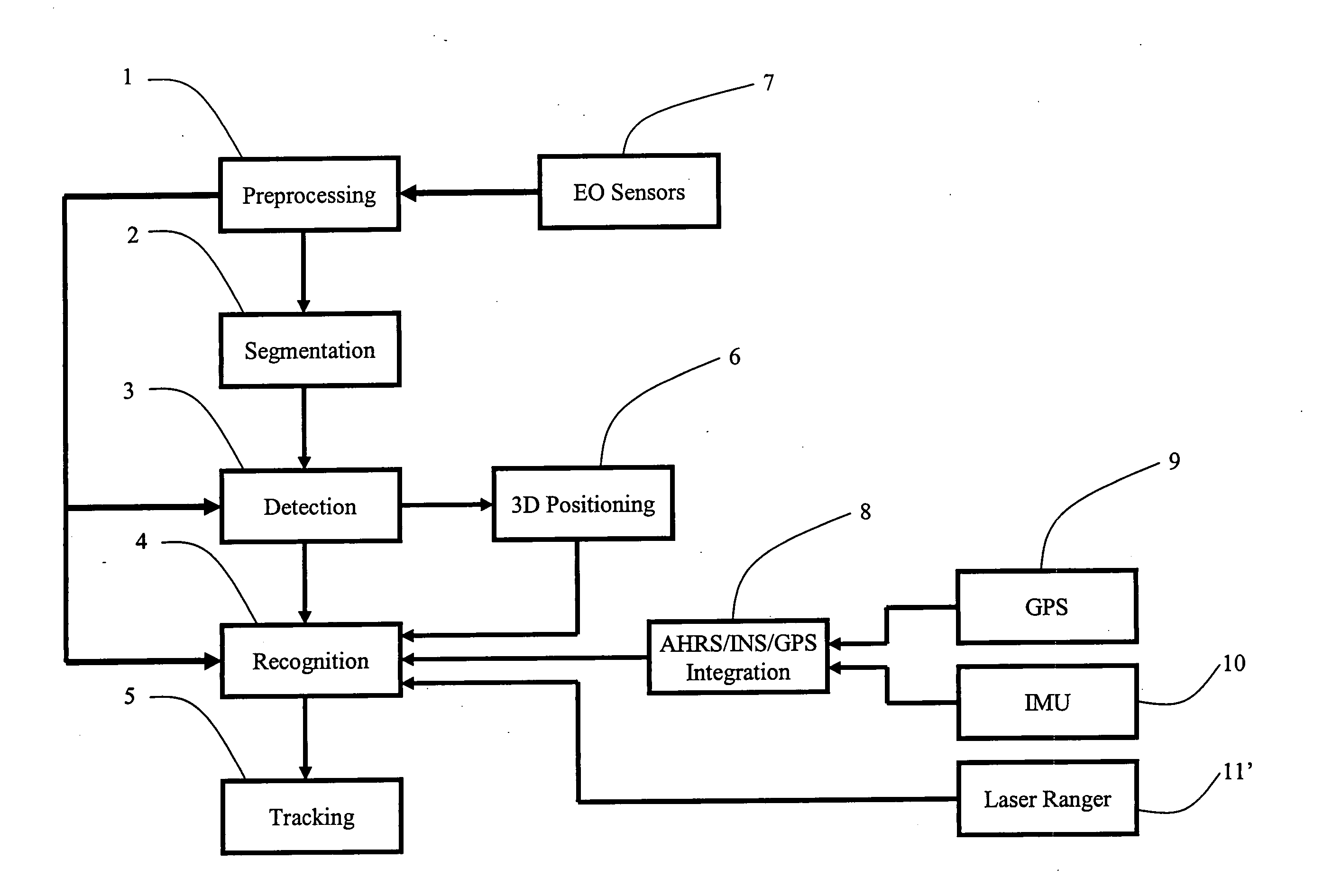
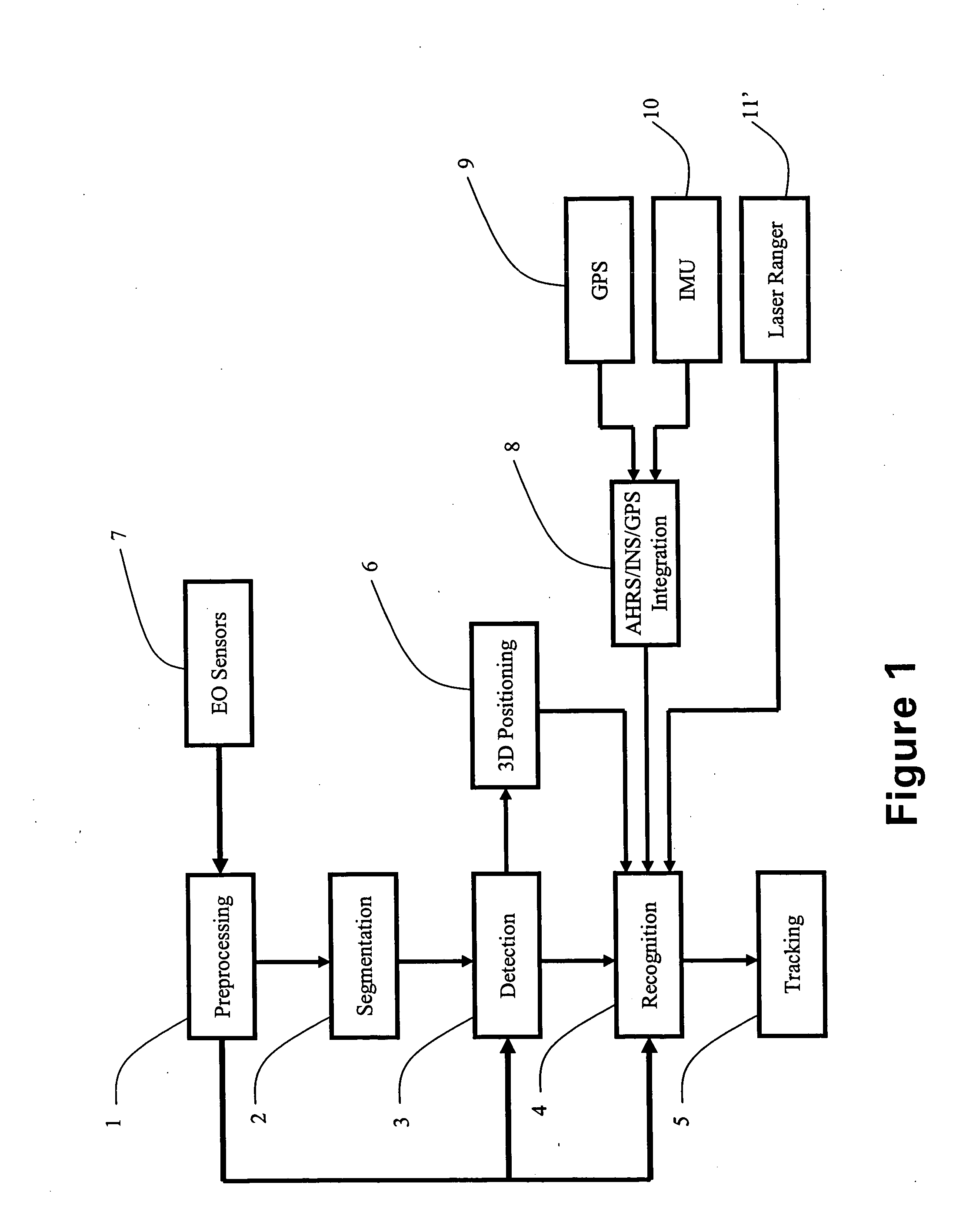
Generally, IMU / GPS integration can output the position, attitude and azimuth of the vehicle itself. A laser ranger measures the distance between the object and vehicle. Electro-optic image sensors derive the 3D environment in the field of view. The traditional electro-optic sensor image processing is time consuming and unreliable.

Referring to FIG. 1, the electro-optic sensor image processing comprises a preprocessing module 1, a segmentation module 2, a detection module 3, a recognition module 4, a 3D-positioning module 5, a tracking module 6, EO sensors 7, an AHRS / INS / GPS Integration module 8, a GPS receiver 9, a MEMS IMU 10, and a laser ranger 11.

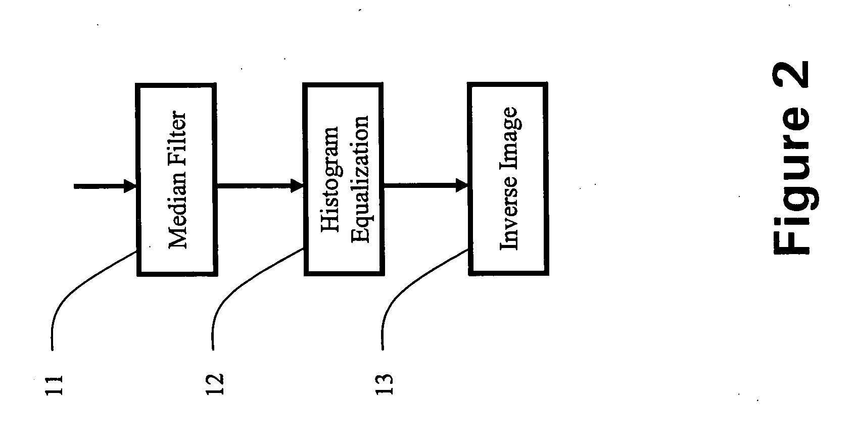
Referring to FIG. 2, the preprocessing module 1 comprises a Median Filter module 11, a Histogram Equalization module 12 and an Inverse Image module 13.

Referring to FIG. 3, the segmentation module 2 comprises a Threshold Black / White module 21, a Suppress Black module 22, a Suppress White module 23, and a Sobel Filter module 24.

Edg...


PUM


Abstract

An object positioning solves said problems encountered in machine vision, which employs electro-optic (EO) image sensors enhanced with integrated laser ranger, global positioning system/inertial measurement unit, and integrates these data to get reliable and real time object position. An object positioning and data integrating system comprises EO sensors, a MEMS IMU, a GPS receiver, a laser ranger, a preprocessing module, a segmentation module, a detection module, a recognition module, a 3D positioning module, and a tracking module, in which autonomous, reliable and real time object positioning and tracking can be achieved.

Description

FIELD OF THE PRESENT INVENTION The present invention relates generally to machine vision systems, and more particularly to object positioning, which employs electro-optic (EO) image sensors enhanced with integrated laser ranger, global positioning system / inertial measurement unit, and integrates this data to get reliable and real time object position. BACKGROUNG OF THE PRESENT INVENTION There are two difficult problems for machine vision systems. One is image processing speed, another is the reliability, which affect the application of electro-optic image sensors (e.g. stereo cameras) to robotics, autonomous landing and material handling. The match filter takes long time to match different orientation and size templates to detect certain object. In the present invention, the electro-optic image sensor imaging system derives the electro-optic image sensors' attitude and orientation data from a global positioning system / inertial measurement unit integrated navigation system for the...

Claims


Application Information

Patent Timeline
IPC IPC(8): G06K9/00G06K9/46G06K9/62G06T7/00
CPCG06K9/3216G06T7/0044G06K9/6293G06T7/74G06V10/245G06F18/256
Inventor HU, GUOHUICOLEMAN, NORMANLIN, CHING-FANG
Owner AMERICAN GNC
Why Eureka
Try Eureka