Semiconductor waste gas processing device with flame path

Inactive Publication Date: 2005-02-10
FENG WU NIANG
View PDF3 Cites 14 Cited by
  • Summary
  • Abstract
  • Description
  • Claims
  • Application Information

AI Technical Summary

Benefits of technology

[0006] Accordingly, the primary object of the present invention is to provide a semiconductor waste gas processing device with a flame path for cleaning waste gas effectively and preventing inner side of body from erosion.

Problems solved by technology

Moreover, after the high temperature is burnt, the combustible harmful material will become ash which will adhere on the inner side of body.
After a long time, a thick ash layer is formed so that the waste gas combustion chamber can not be operated normally.
Moreover, the high temperature is as high as 600° C. The fluorine ions in the waste gas have a high erosion at this temperature so as to damage the inner side of body when the waste gas combustion chamber is used for a longer time.

Method used


Image

  • Semiconductor waste gas processing device with flame path
  • Semiconductor waste gas processing device with flame path
  • Semiconductor waste gas processing device with flame path

Examples


first embodiment

[0018] First Embodiment

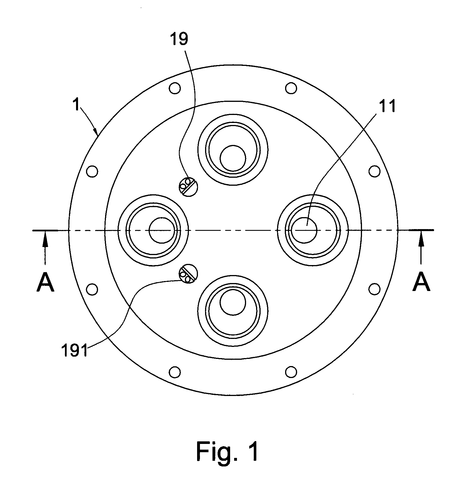
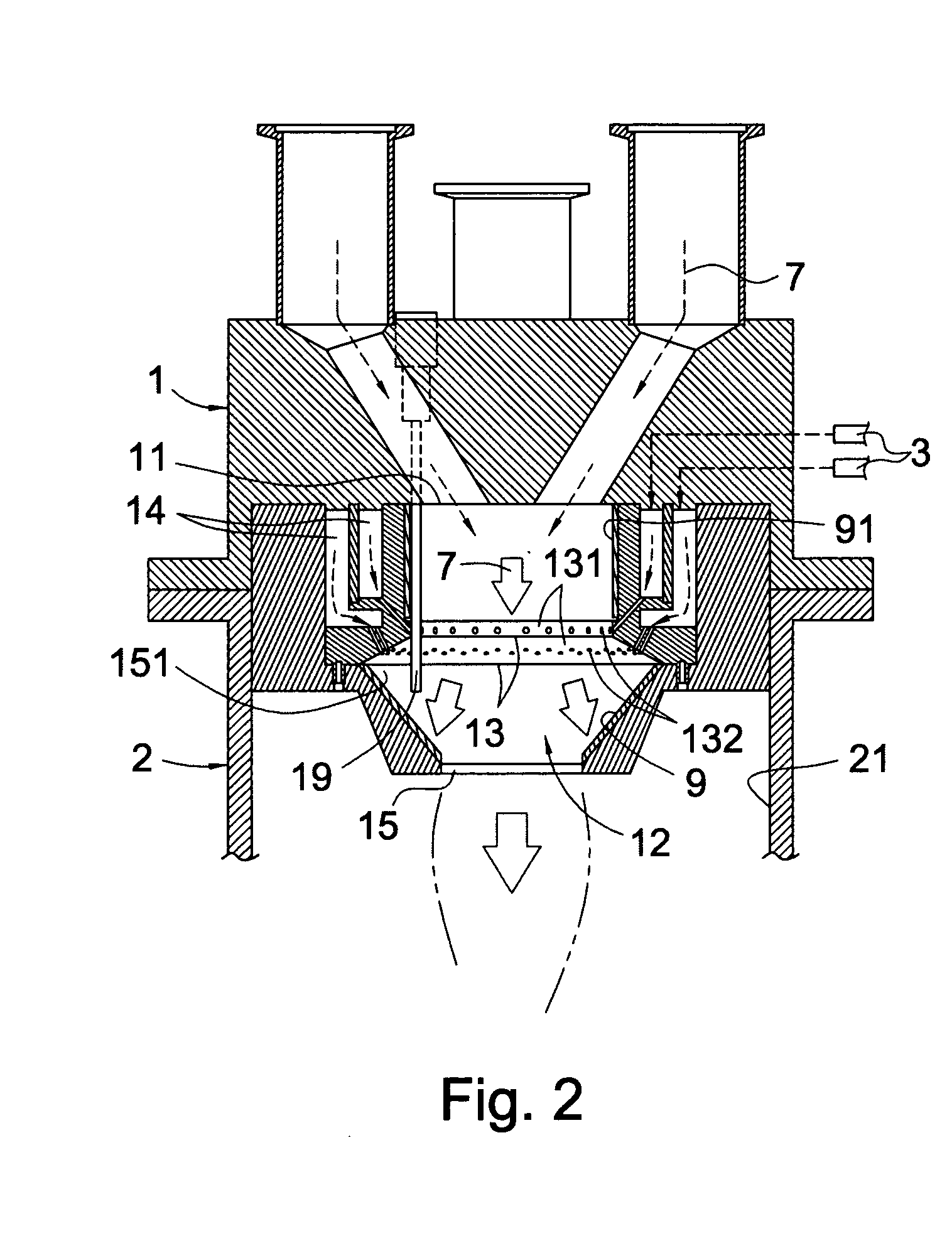
[0019]FIGS. 1 and 2 show a semiconductor waste gas processing device with a flame path of the present invention. The device includes a flame path 12 passing through the waste gas combustion chamber 2, a head section 1 located on a top of the waste gas combustion chamber 2, and a waste gases outlet 11.

[0020] The flame path 12 is formed by at least one layer of fuel spray ring 13. The fuel spray ring 13 is installed with a plurality of secondary flame apertures 132. A secondary flame ring 131 of each fuel spray ring 13 has a plurality of secondary flame apertures 132. The shapes of the secondary flame ring 131 and the plurality of secondary flame apertures 132 may be plane shapes or tapered shapes. A lower end of the flame path 12 is formed with a flame jet 15 which is communicable with the waste gas combustion chamber 2. An internal of the flame jet 15 is formed with a flame capture area 151 which can retain a flame even a large amount of waste gas exists. An ...

second embodiment

[0023]

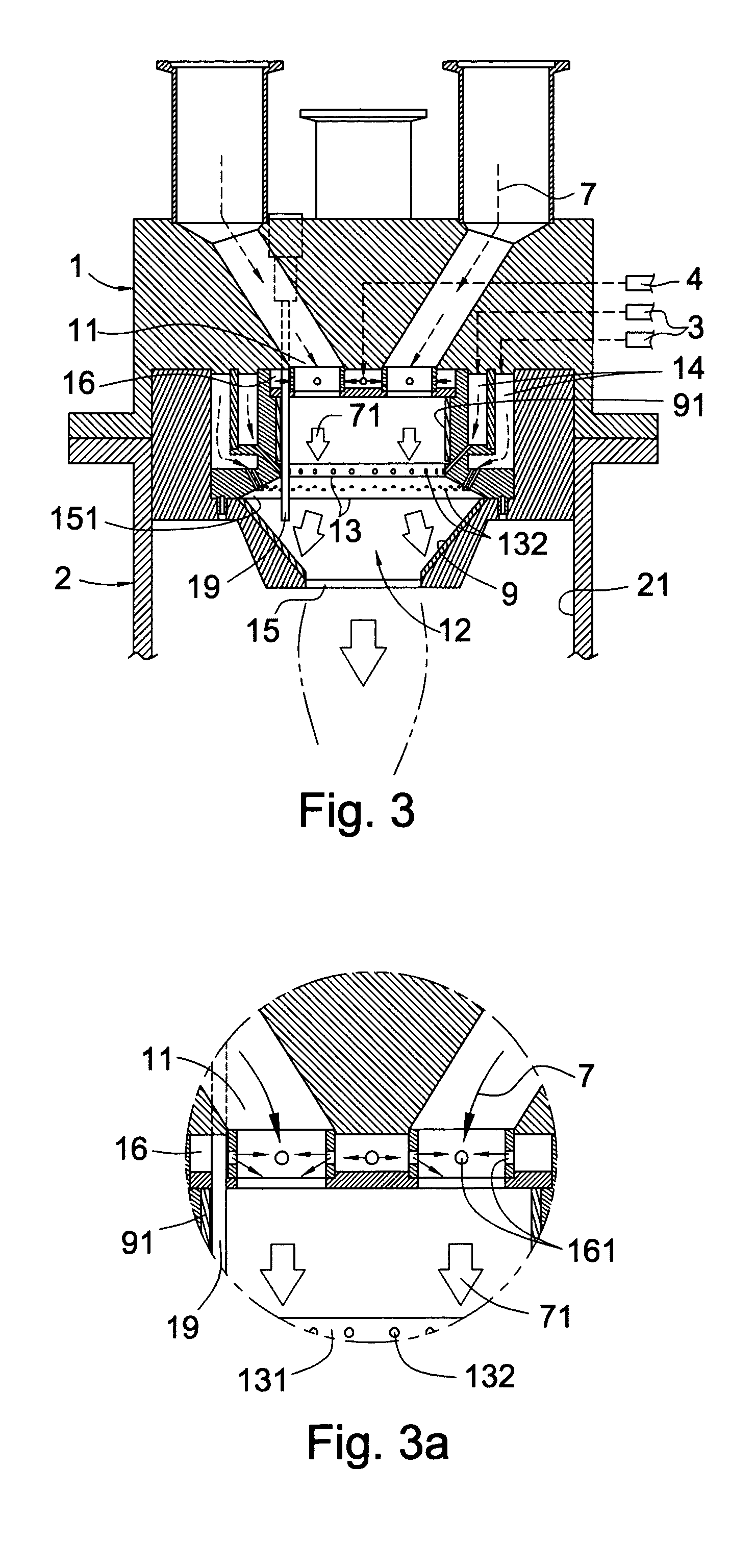
[0024] In the present invention, a plurality of oxygen apertures 161 can be formed at the plurality of waste gases outlets 11 (referring to FIGS. 3 and 3(a)) so that one end of each oxygen aperture 161 is communicable to the respective waste gases outlet 11 and another end of the oxygen aperture 161 is communicable with one oxygen (or fuel) room 16. A oxygen source line 4 is connected to the flame path 12 for supplying pure oxygen (or fuel gas) so that the waste gas 7 can mix with the pure oxygen (or fuel gas) so as to form as gas mixing room 71. By containing oxygen or fuel gas in the waste gases outlet 11, when the waste gas 7 flows through the fire nets, the harmful materials in the waste gas 7 will be burnt out or cleaned.

third embodiment

[0025] Third Embodiment

[0026] In the present invention, an annular water room 17 (referring to FIG. 4) is formed in the periphery of the fuel room 14 in the head section 1. A water source line 5 for supplying high pressure water flow is connected to the water room 17. A bottom of the water room 17 is installed with a plurality of water spray apertures 171 so that the plurality of water spray apertures 171 is communicable to the waste gas combustion chamber 2. Moreover, a periphery of the water room 17 is formed with an annular air room 18 (referring to FIG. 4). A high pressure air source line 6 is connected to the air room 18 for supplying high pressure air. A bottom of the air room 18 is formed with a plurality of air spray apertures 181 which are aligned to the outlet of the water spray aperture 171 to be communicable to the waste gas combustion chamber 2. By above structure, the high pressure water flow injecting into the waste gas combustion chamber 2 from the water spray apertu...


PUM

PropertyMeasurementUnit
Temperatureaaaaaaaaaa

Abstract

A semiconductor waste gas processing device comprises a flame path through a waste gas combustion chamber, a head section on a top of the waste gas combustion chamber, and a waste gases outlet. The flame path comprises at least one layer of fuel spray ring; each fuel spray ring having a respective fuel room formed in the head section and being connected to a fuel source line for supplying fuel gas; a secondary flame ring of each fuel spray ring having a plurality of secondary flame apertures; a tapered flame jet which is communicable with the waste gas combustion chamber being formed in a lower end of the flame path and an igniter being installed in the flame path.

Description

FIELD OF THE INVENTION [0001] The present invention relates to waste gas processing devices, and particularly to a semiconductor waste gas processing device with a flame path for cleaning waste gas effectively and preventing the inside of body from erosion. BACKGROUND OF THE INVENTION [0002] In the semiconductor manufacturing process, waste gas contains fluorine gas with strong erosion. The ions of the gas must be decomposed under a high temperature of 1000° C. so as to form harmless gases. In the prior art, fuel gas is injected into a waste gas combustion chamber from a head section. The fuel is fired in an outlet of the head section so that a high temperature flame is formed in the waste gas combustion chamber for thermally decomposing the fluorine ions into harmless gas. Thereby, the waste gas is cleaned. [0003] The flame is low density flame and the waste gas can pass through the gaps between the flame. The firing area is only confined at the outlet of the waste gas combustion c...

Claims


Application Information

Patent Timeline
IPC IPC(8): B01D53/68
CPCB01D2258/0216B01D53/68
Inventor FENG, WU NIANG
Owner FENG WU NIANG
Why Eureka
Try Eureka