Fuel cell system and fuel feeder

a fuel cell and feeder technology, applied in the direction of liquid degasification, separation processes, electrochemical generators, etc., can solve the problems of excessive harmful substances, reduce the amount of harmful substances discharged, and effectively adsorb the

Inactive Publication Date: 2005-02-10
SANYO ELECTRIC CO LTD
View PDF2 Cites 26 Cited by
  • Summary
  • Abstract
  • Description
  • Claims
  • Application Information

AI Technical Summary

Benefits of technology

[0008] An aspect of the present invention relates to a fuel cell system. The fuel cell comprises a fuel cell device operating with a liquid fuel and an adsorption unit for adsorbing harmful substances contained in a fluid discharged from the fuel cell device. Harmful substances such as formaldehyde formed in the fuel cell device can be adsorbed by the adsorption unit to minimize the amount of the harmful substances discharged from the system, resulting in a safe fuel cell system.
[0009] The adsorption unit may be disposed in an exhaust unit for discharging a gas from the fuel cell system. The exhaust unit has a structure for exhausting such as a tubing for discharging a gas and an outlet. An exhaust may pass through the adsorption unit before being discharged from the outlet, to reduce the amount of harmful substances discharged. The adsorption unit may be disposed in a flow line for the liquid fuel. When feeding a liquid fuel to a fuel cell device while circulating the fuel, the adsorption unit may be disposed on the circulation line so that the adsorption unit can adsorb and remove harmful substances formed in the fuel cell device during circulation.
[0010] The adsorption unit may be replaceable. When harmful substances exceeding an adsorption capacity of the adsorption unit are formed, the harmful substances may be discharged from the system without being adsorbed. However, the excessive harmful substances can be effectively adsorbed by replacing the adsorption unit. The fuel cell system may further comprise a fuel feeder for feeding a liquid fuel to the fuel cell device and the adsorption unit may be integrated with the fuel feeder. Thus, during replacing the fuel feeder, the adsorption unit can be simultaneously replaced to prevent harmful substances from being discharged from the system due to saturated adsorption capacity of the adsorption unit.

Problems solved by technology

However, the excessive harmful substances can be effectively adsorbed by replacing the adsorption unit.

Method used


Image

  • Fuel cell system and fuel feeder
  • Fuel cell system and fuel feeder
  • Fuel cell system and fuel feeder

Examples


embodiment 1

[0022] Embodiment 1

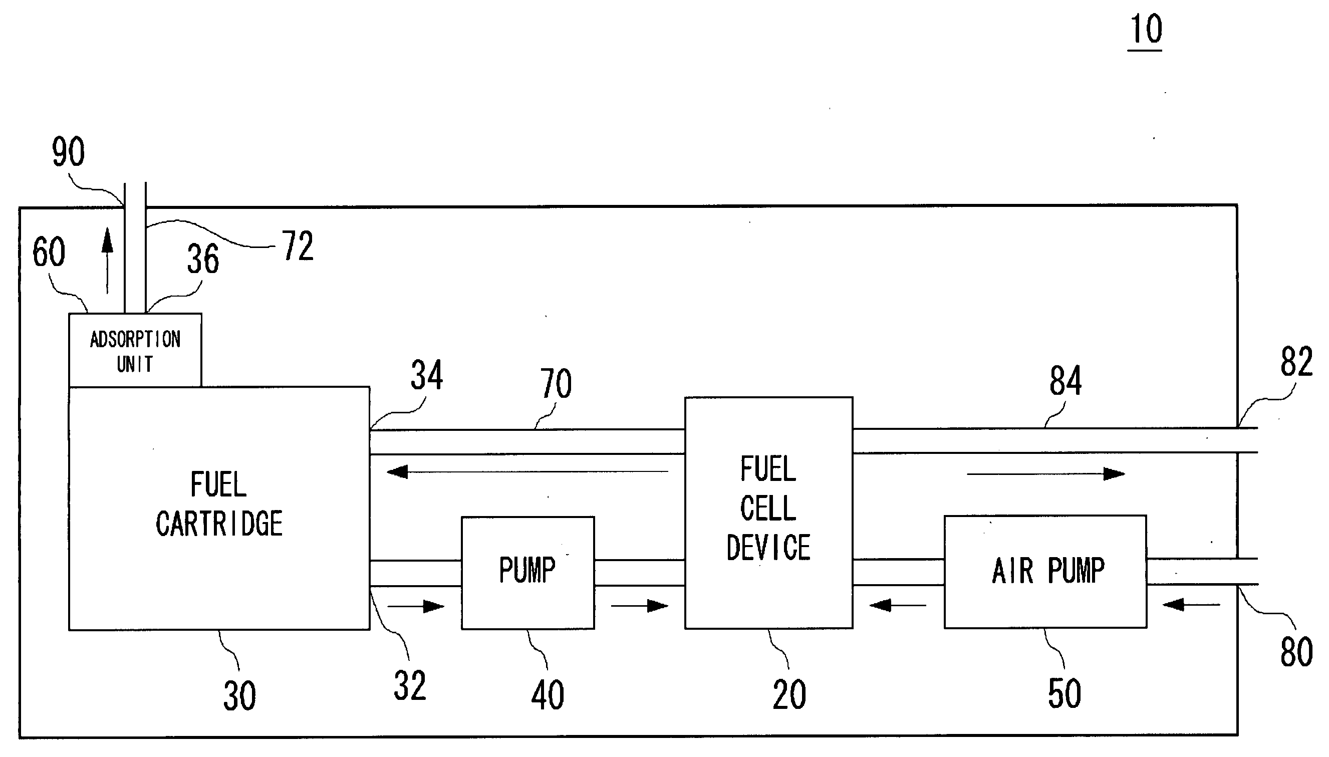
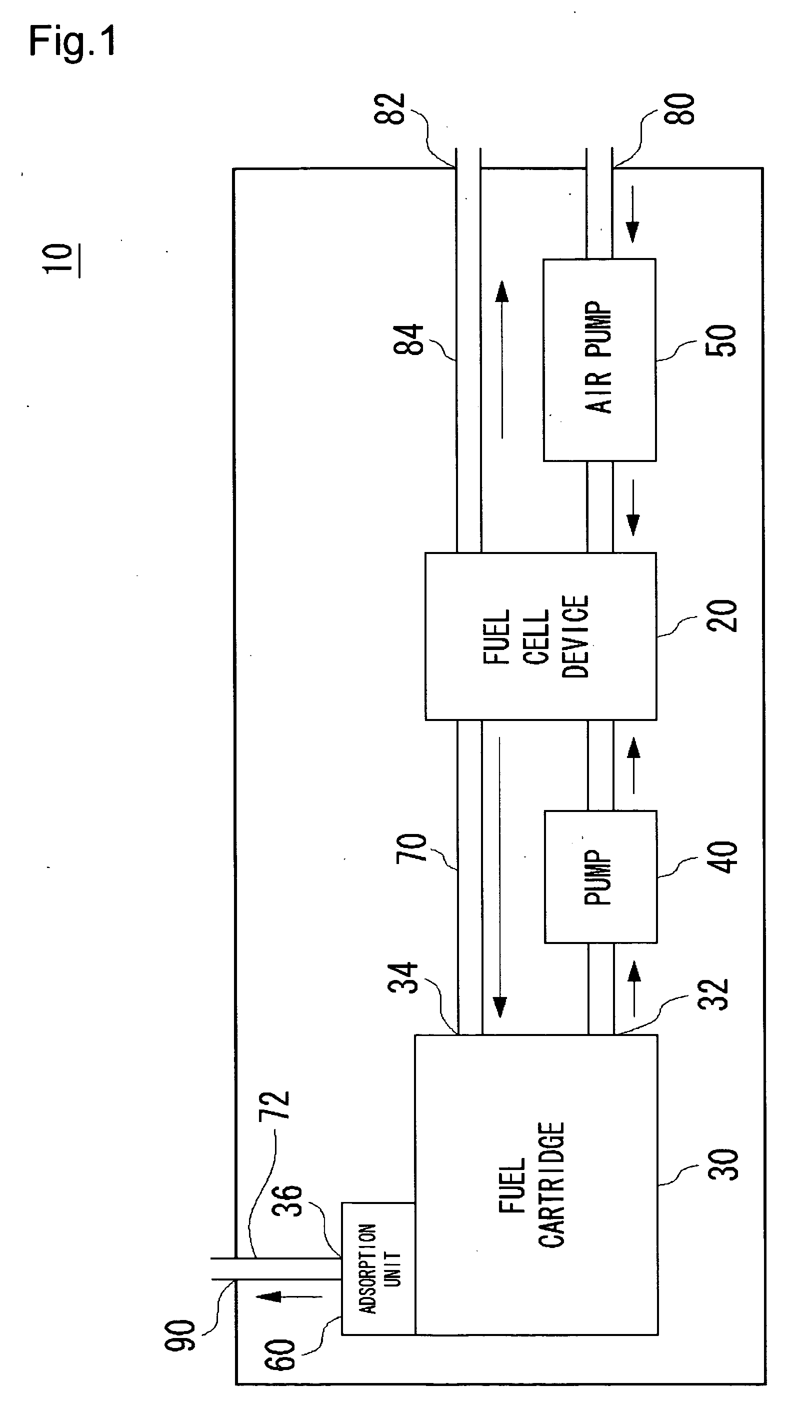
[0023]FIG. 1 shows a general structure of a fuel cell system 10 according to Embodiment 1. The fuel cell system 10 comprises a fuel cell device 20; a fuel cartridge 30 as an example of a fuel feeder for feeding a liquid fuel to the fuel cell device 20; a pump 40 for diluting the liquid fuel in the fuel cartridge 30 and feeding it to the fuel cell device 20; an air pump 50 for feeding air to the fuel cell device 20; and an adsorption unit 60 for adsorbing harmful substances. The fuel cell device 20 comprises a stack in which a plurality of a membrane electrode assemblies (hereinafter, referred to as “MEA”) consisting of a cathode and an anode layers and a proton-conductive solid polymer electrolyte film such as Nafion® between them are laminated via a conductive separator. An unreformed liquid fuel such as alcohols (e.g., methanol and ethanol) and ethers is directly fed to an anode (fuel electrode) in the MEA, while air is fed to a cathode (air electrode) of the ME...

embodiment 2

[0032] Embodiment 2

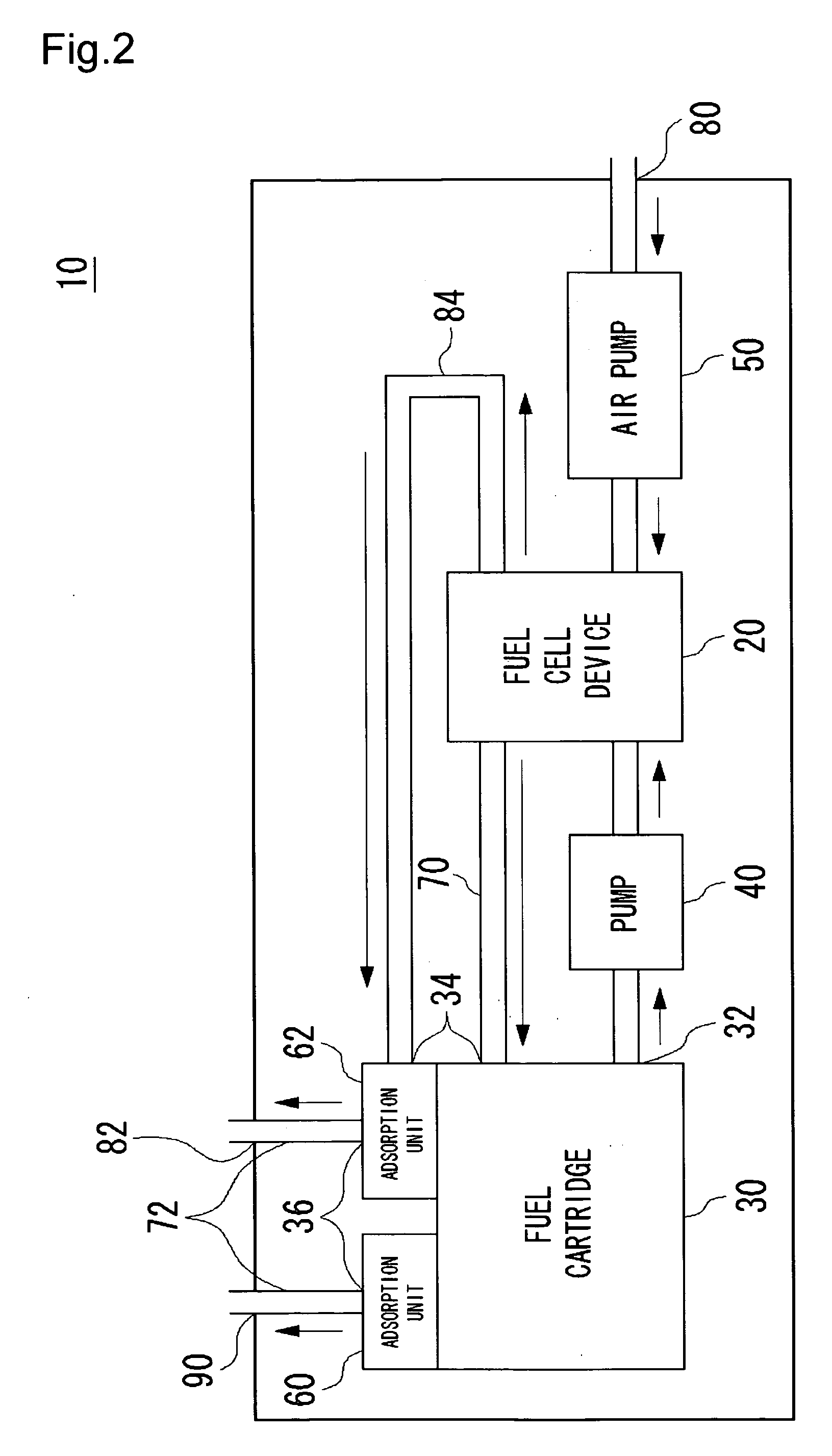
[0033]FIG. 2 shows a general structure of a fuel cell system 10 according to Embodiment 2. The fuel cell system 10 of this embodiment comprises, in addition to the fuel cell system 10 of Embodiment 1 shown in FIG. 1, an additional adsorption unit 62 in a vent 82 in the air electrode side. The other components are as described for Embodiment 1 and corresponding components are denoted by the same symbols.

[0034] As described above, an organic liquid fuel may move through a solid polymer electrolyte membrane toward the air electrode side, also generating harmful substances in the air electrode side. Therefore, in this embodiment, there is disposed the adsorption unit 62 integrally formed with the fuel cartridge 30 between a tubing 84 from the air electrode and the vent 82. It can properly treat a trace amount of harmful substances generated in the air electrode to prevent them from being discharged from the system. Thus, a safer fuel cell system 10 can be provided. T...

embodiment 3

[0036] Embodiment 3

[0037]FIG. 3 shows a general structure of a fuel cell system 10 according to Embodiment 3. The fuel cell system 10 of this embodiment has a structure as described in Embodiment 2 shown in FIG. 2, except that the adsorption unit 60 also serves as the adsorption unit 62. The other components are as described for Embodiment 2 and corresponding components are denoted by the same symbols.

[0038] In this embodiment, a tubing 84 in the air electrode side is connected to the adsorption unit 60 and a gas exhausted from the air electrode in the fuel cell device 20 is discharged from a vent 90 through the adsorption unit 60. Thus, a safe fuel cell system 10 can be provided. Furthermore, since adsorption unit 60 also serves as the adsorption unit 62, the structure may be simplified to make the fuel cartridge 30 more compact and lighter.


PUM

PropertyMeasurementUnit
adsorptionaaaaaaaaaa
electric poweraaaaaaaaaa
energyaaaaaaaaaa

Abstract

The present invention provides a safe fuel cell system. The fuel cell system comprises a fuel cell device operating with an organic liquid fuel; a fuel cartridge for feeding the organic liquid fuel to the fuel cell device; a pump for feeding the organic liquid fuel in the fuel cartridge to the fuel cell device while diluting the fuel; an air pump for feeding air to the fuel cell device; and an adsorption unit for adsorbing harmful substances generated from a reaction in the fuel cell device. For discharging a gas from the system, the gas is flown through the adsorption unit for adsorption of harmful substances and then discharged from a vent.

Description

BACKGROUND OF THE INVENTION [0001] 1. Field of the Invention [0002] The present invention relates to a fuel cell system. In particular, it relates to a fuel cell system using a liquid fuel and a fuel feeder available for the fuel cell system. [0003] 2. Description of the Related Art [0004] In recent years, a direct methanol fuel cell (DMFC) has come to attract attention as a type of fuel cell. A DMFC generates electric power by directly feeding methanol as an unreformed fuel for an electrochemical reaction between methanol and oxygen. Methanol has higher energy per a unit volume than hydrogen and is suitable for storage and relatively non-explosive. Thus, it is expected to be used in a power source for an automobile, a cellular phone or the like (See Patent Reference 1). [0005] In a DMFC, a reaction generating carbon dioxide and hydrogen ions from methanol and water proceeds in an anode (fuel electrode), while a reaction generating water from oxygen in the air and hydrogen ions proc...

Claims


Application Information

Patent Timeline
Patent Type & Authority Applications(United States)
IPC IPC(8): H01M8/10B01D19/00B01D53/02H01M8/04H01M8/06
CPCB01D19/0068B01D53/02Y02E60/50H01M8/04201H01M8/04208H01M8/04186H01M8/04H01M8/06
Inventor KABUMOTO, HIROKIKANAI, HIROKO
Owner SANYO ELECTRIC CO LTD
Why Eureka
Try Eureka