System to measure density, specific gravity, and flow rate of fluids, meter, and related methods

a technology of density measurement and flow rate, applied in the field of flow meters, can solve the problems of high cost and complexity of density measurement techniques, high cost and high cost of densitometers, and the need for frequent maintenance by highly skilled technicians

Active Publication Date: 2005-02-17
SAUDI ARABIAN OIL CO
View PDF10 Cites 76 Cited by
  • Summary
  • Abstract
  • Description
  • Claims
  • Application Information

AI Technical Summary

Benefits of technology

Advantageously an embodiment of the present invention can provide an instrument intended for use in industrial combustion processes using low molecular weight...

Problems solved by technology

Density measurement techniques are typically expensive and complex.
However, both of these densitometers, though very accurate, are very costly and require highly skilled technicians to conduct frequent maintenance.
The typical gas chromatographs can provide 0.1% accuracy but are very complex.
Flame BTU analyzers can give between 0.4-2.0% accuracy but are also very complex.
The meters, however, typically cannot accurately measure low molecular weight gas density.
Thus, it is not possible to derive density or mass flow rate from the volumetric flow rate measurement, alone, especially where the fluid is in a gaseous form.
Because it requires breaching the production pipe for each of the static and dynamic ports of the differential pressure measuring device, however, the device, is complex to install.
Addit...

Method used


Image

  • System to measure density, specific gravity, and flow rate of fluids, meter, and related methods
  • System to measure density, specific gravity, and flow rate of fluids, meter, and related methods
  • System to measure density, specific gravity, and flow rate of fluids, meter, and related methods

Examples


Embodiment Construction

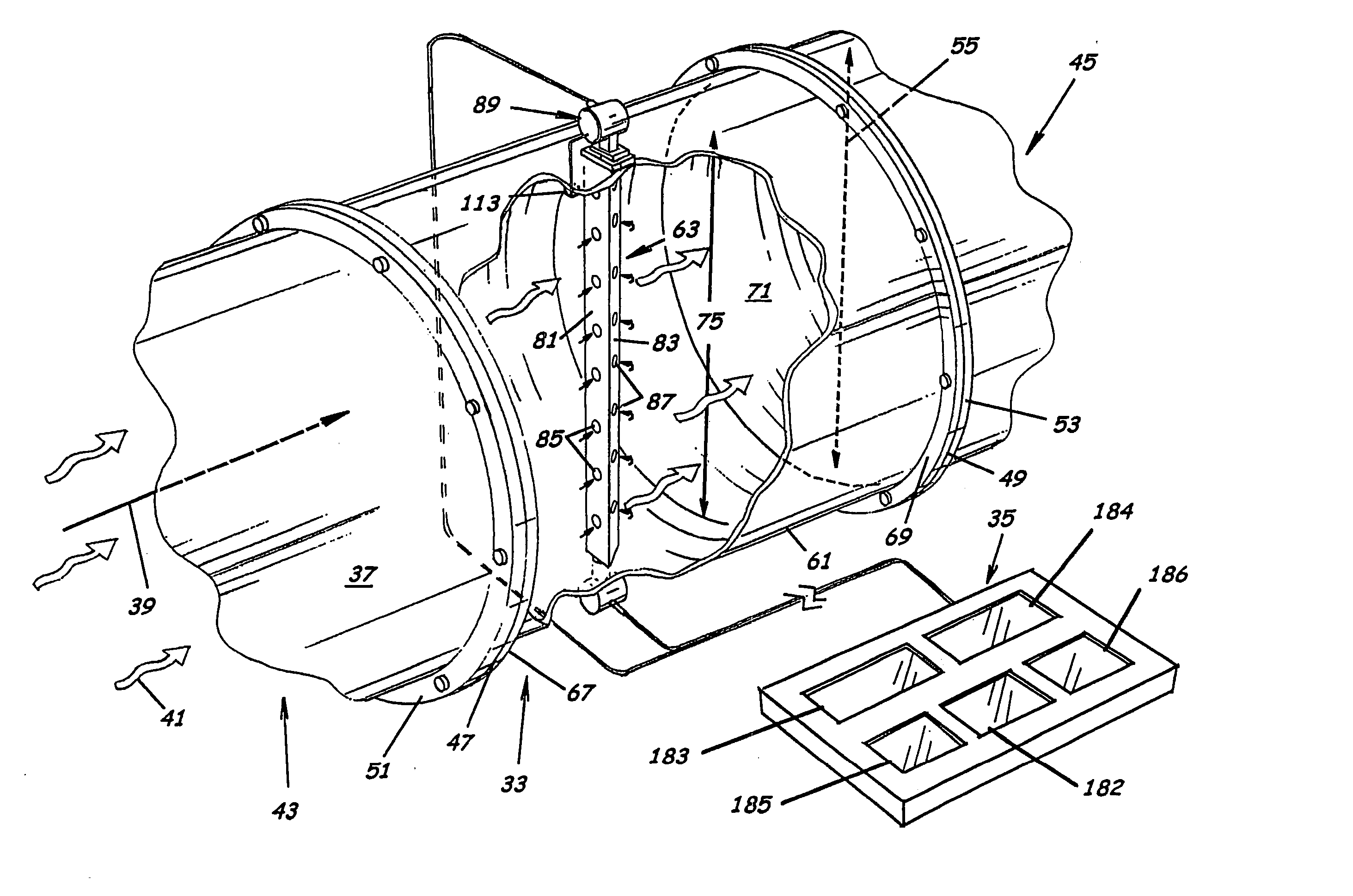
The present invention will now be described more fully hereinafter with reference to the accompanying drawings, which illustrate embodiments of the invention. This invention may, however, be embodied in many different forms and should not be construed as limited to the illustrated embodiments set forth herein. Rather, these embodiments are provided so that this disclosure will be thorough and complete, and will fully convey the scope of the invention to those skilled in the art. Like numbers refer to like elements throughout. Prime notation, if used, indicates similar elements in alternative embodiments. Note, the term “adjacent” as used herein refers to a position that is within, on, or near the object referenced.

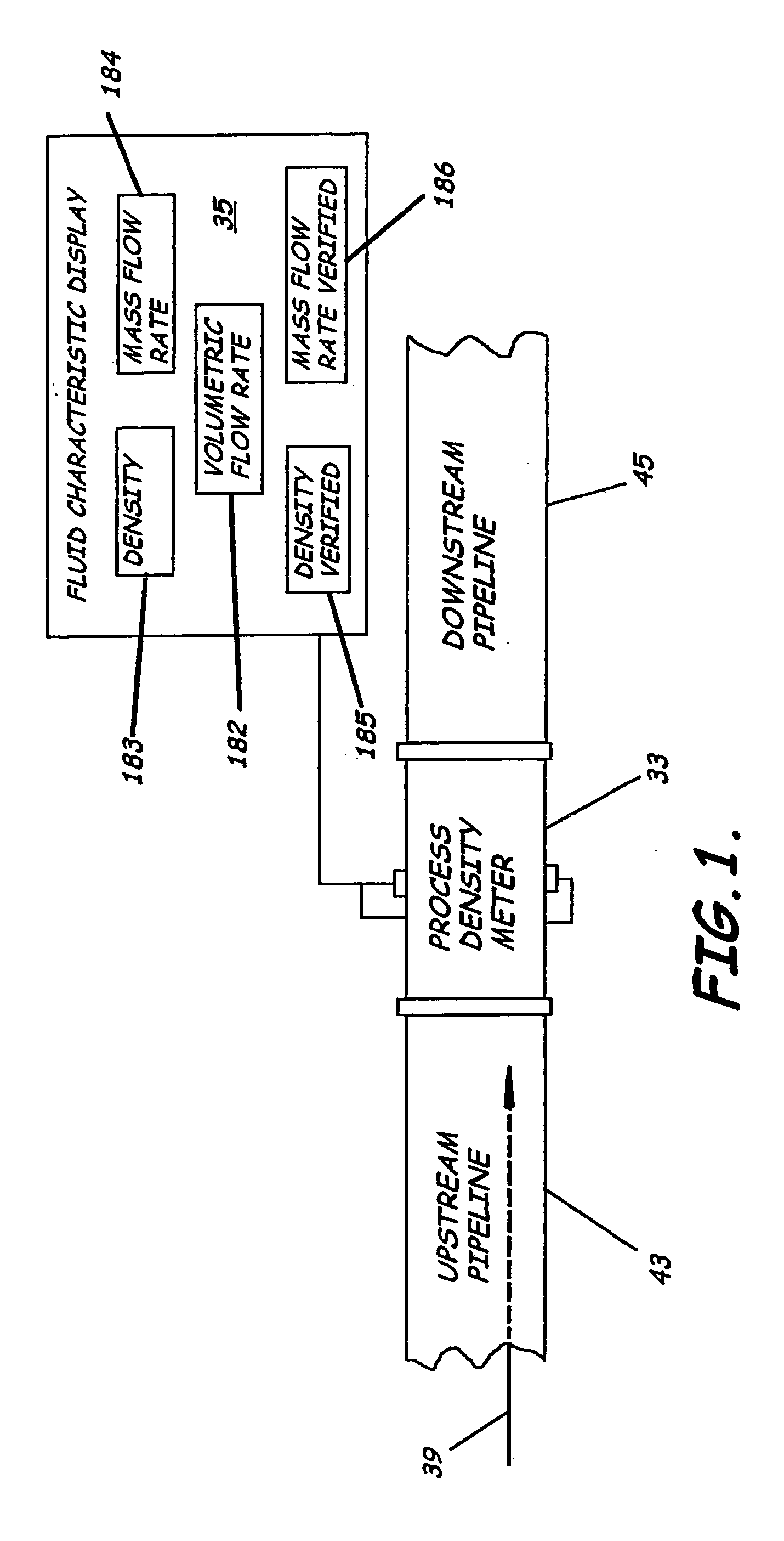
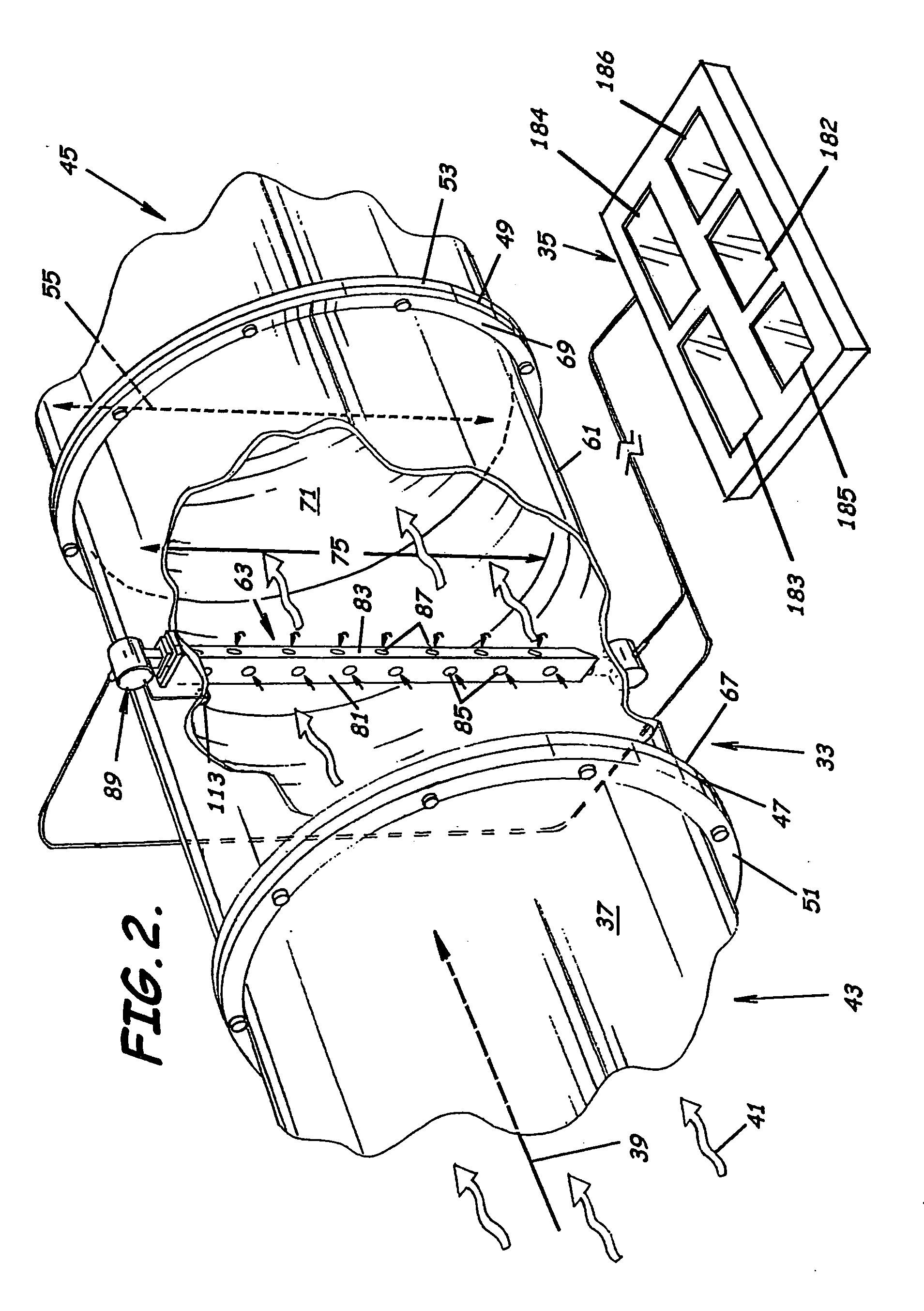
As illustrated in FIGS. 1-14, embodiments of the present invention advantageously provide a system, meter, and methods for measuring fluid flow characteristics in a pipeline. In particular, the flow characteristics of primary interest relate to industrial combustion pro...


PUM


Abstract

A system to measure fluid flow characteristics in a pipeline, meter, and methods includes a pipeline having a passageway to transport flowing fluid therethrough, a process density meter including at least portions thereof positioned within the pipeline to provide flowing fluid characteristics including volumetric flow rate, fluid density, and mass flow rate of the flowing fluid, and a fluid characteristic display to display the fluid characteristics. The process density meter includes a vortex-shedding body positioned within the pipeline to form vortices and a vortex meter having a vortex frequency sensor to measure the frequency of the vortices and to determine the volumetric flow rate. The process density meter further includes a differential pressure meter positioned adjacent the vortex-shedding body to produce a differential pressure meter flow rate signal indicative of the density of fluid when flowing through the pipeline. The process density meter also includes a thermal flow meter positioned adjacent the vortex-shedding body to produce a mass flow rate signal indicative of the mass flow rate of fluid when flowing through the pipeline. The process density meter produces an output of a volumetric flow rate, a flowing fluid density, and a mass flow rate to be displayed by the fluid characteristic display.

Description

BACKGROUND OF THE INVENTION 1. Field of the Invention The present invention relates generally to flow meters. In more specific aspects, the present invention relates to the measurement of the density, specific gravity, and flow rate of flowing fluids, systems, apparatus and methods. 2. Description of the Related Art Many industrial facilities feed fuel gases to their industrial combustion processes. Particularly, these fuel gases tend to be low molecular weight hydrocarbon fuel gases. These fuel gases typically have a constantly changing hydrocarbon composition. To maintain an efficient fuel-air ratio combustion control, the hydrocarbon density, directly related to specific gravity, and thus, the BTU content, must be known. Density measurement techniques are typically expensive and complex. Most industrial combustion processes with varying composition fuel gases use either gas chromatographs or vibrating spool densitometers to determine fuel gas density. However, both of these d...

Claims


Application Information

Patent Timeline
IPC IPC(8): G01F1/32G01F1/86G01N9/00
CPCG01F1/3209G01F1/3254G01N9/00G01F1/86G01F1/3272G01F1/3273G01F1/3259
Inventor SPRAGUE, JAMES L.
Owner SAUDI ARABIAN OIL CO
Why Eureka
Try Eureka