Processing apparatus having integrated pumping system

a technology of processing apparatus and pumping system, which is applied in the direction of pumping plants, efficient regulation technologies, machines/engines, etc., can solve the problems of large space problem associated with large conventional pumps, contamination and heat generation necessitate, and equipment nearby is subject to the discharge of heat and particles from the pump, so as to increase space efficiency

Inactive Publication Date: 2005-02-17
APPLIED MATERIALS INC
View PDF12 Cites 24 Cited by
  • Summary
  • Abstract
  • Description
  • Claims
  • Application Information

AI Technical Summary

Benefits of technology

[0015] In another aspect of the invention, a substrate processing apparatus is provided that includes an integrated pumping system wherein the pumps are dispersed within a clean room and within the envelop or footprint of the apparatus. The pumps are locatable in a variety of positi

Problems solved by technology

The space problem associated with the large conventional pumps is magnified by the fact that the pumps are not designed to service more than one chamber and, therefore, each chamber requires its own dedicated pump.
One problem associated with conventional pumps is contamination and heat generation which necessitate their separation from the processing apparatus.
With no enclosure to separate the inner workings of the pump from the surrounding environment, any equipment nearby is subject to the discharge of heat and particles from the pump.
Conventional low and pre-vacuum pumps are also heavy, noisy and cause vibration.
This level of vibration is not allowable near a process apparatus where robot arms are moving delicate wafers to and from process stations and wafer structures are being created in the 0.18-0.25 10−6 m range.
However, the large diameter stainless steel pipe is expensive and a long length of pipe can cost as much as the pump itself.
In addition, the large number of elbow joints and connections in the long foreline extending from the clean room to a separate room, have to be carefully sealed with non-corrodible gas seals to avoid leaks and releasing hazardous and

Method used


Image

  • Processing apparatus having integrated pumping system
  • Processing apparatus having integrated pumping system
  • Processing apparatus having integrated pumping system

Examples


Embodiment Construction

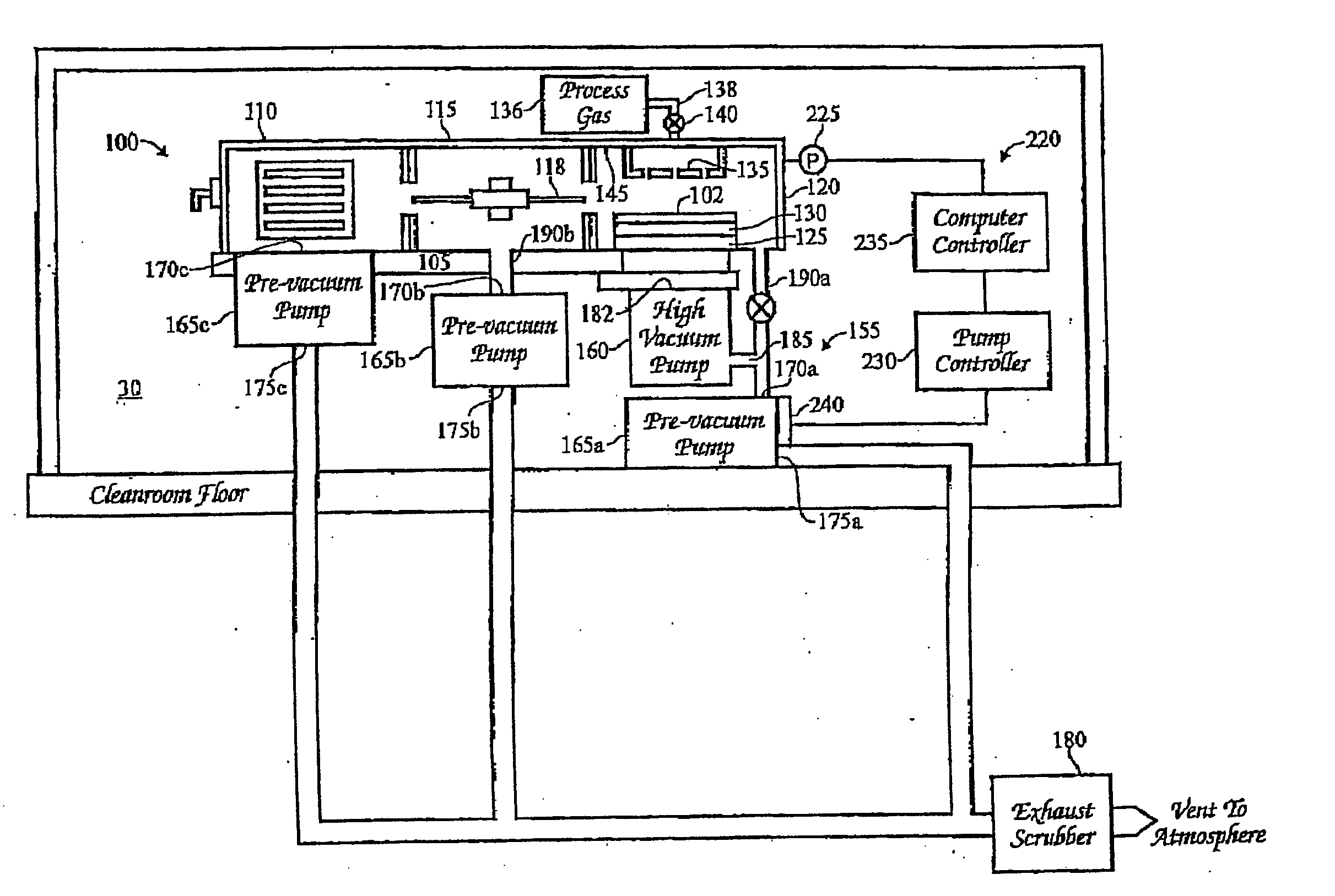
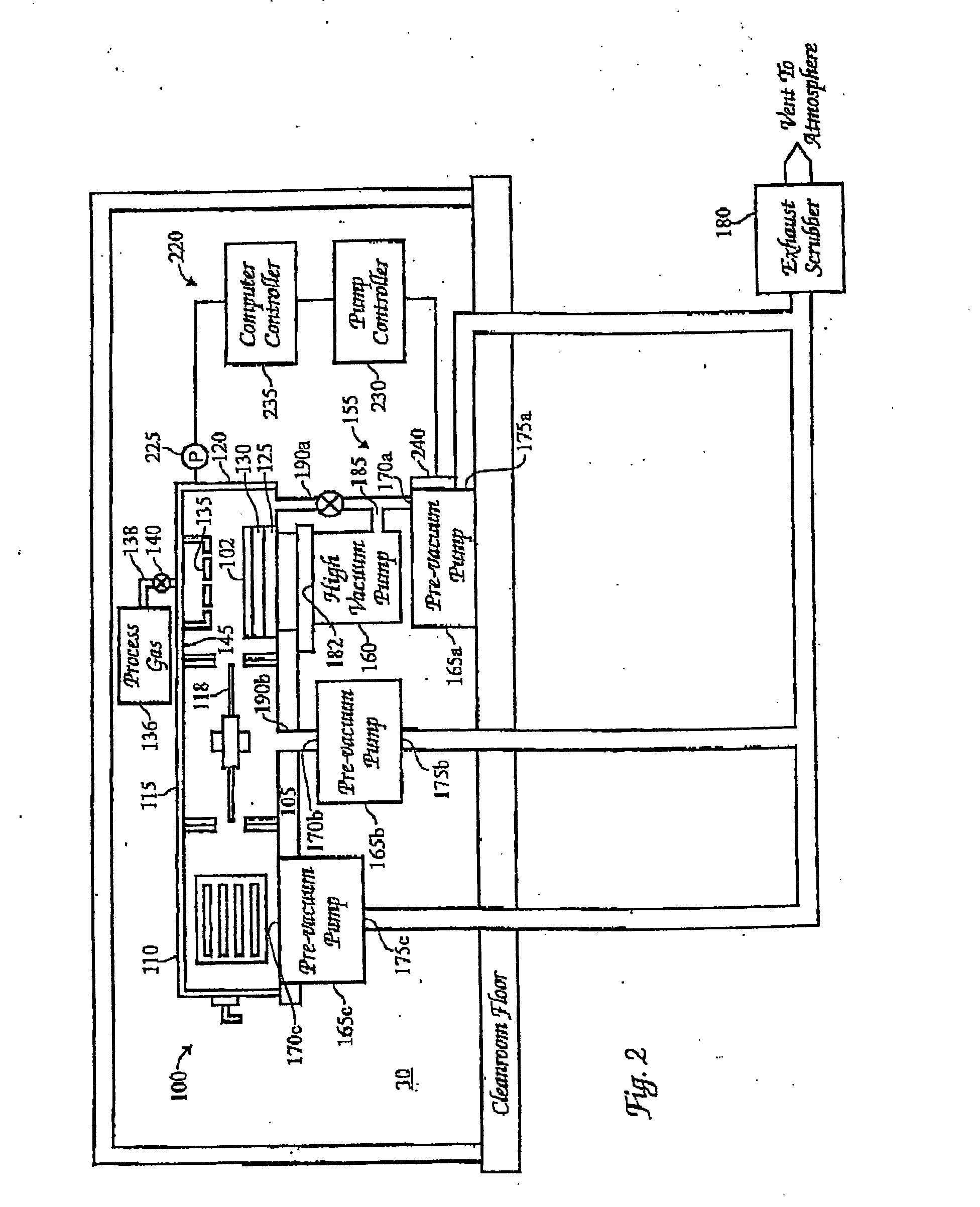
[0042] An exemplary apparatus 100 according to the present invention for processing a substrate 20, such as a silicon wafer, is illustrated in FIG. 2. The apparatus 100 comprises a platform 105 having a plurality of chambers each of which are shaped and sized to hold or enclose one or more substrates 20 (not visible). The chambers are interfaced to one another and typically include load-lock chambers 110, a transfer chamber 115, and process chambers 120, that are mounted contiguously with openings to transfer substrates therebetween. The load-lock chambers 110 hold cassettes that contain batches of substrates 20. The centrally located transfer chamber 115 comprises a robot arm 118 which picks up and transfer substrates 20 from the cassette in the load-lock chamber 110 into a process chamber 120, and after processing of the substrate in the chamber 120, transfers the substrate to other process chambers (not shown) on the platform 105. When the substrate 20 has finished processing, th...


PUM

PropertyMeasurementUnit
Poweraaaaaaaaaa
Poweraaaaaaaaaa
Poweraaaaaaaaaa

Abstract

An apparatus 115 for processing a substrate 20, comprises an integrated pumping system 155 having a high operating efficiency, small size, and low vibrational and noise levels. The apparatus 115 comprises a chamber, such as a load-lock chamber 110, transfer chamber 115, or process chamber 120. An integrated pump 165 is abutting or adjacent to one of the chambers 110, 115, 120 for evacuating gas from the chambers. In operation, the pump is located within the actual envelope or footprint of the apparatus and has an inlet 170 connected to a chamber 110, 115, 120, and an outlet 175 that exhausts the gas to atmospheric pressure. Preferably, the integrated pump 165 comprises a pre-vacuum pump or a low vacuum pump and is housed in a noise reducing enclosure having means for moving the pump between locations and means for stacking pumps vertically in use.

Description

CROSS-REFERENCE TO RELATED APPLICATIONS [0001] This application is a divisional of co-pending U.S. patent application Ser. No. 09 / 505,580, filed Feb. 16, 2000, which claims benefit of U.S. patent application Ser. No. 09 / 220,153, filed Dec. 23, 1998. Each of the aforementioned related patent applications are herein incorporated by reference.BACKGROUND OF THE INVENTION [0002] 1. Field of the Invention [0003] The present invention relates to an apparatus for processing substrates with an integrated pumping system for evacuating gas. [0004] 2. Description of the Related Art [0005]FIG. 1 is a cross sectional view of a conventional apparatus 15 for processing a substrate 20. The apparatus 15 comprises process chambers 25a, transfer chambers 25b, and load-lock chambers 25c mounted contiguously on a platform 28 with openings for transferring substrates between the chambers. In the process chamber 25a, a process gas is used to etch features, deposit layers of material on a substrate 20, or c...

Claims


Application Information

Patent Timeline
IPC IPC(8): B01J3/02F04B37/16F17C13/00F04C25/02F04C28/08H01L21/00H01L21/02H01L21/205H01L21/302H01L21/3065
CPCH01L21/67017H01L21/67167F04D17/168H01L21/6719H01L21/67196H01L21/67184F04D19/04F04D27/0261F04D29/601Y10T137/86163Y10T137/86035Y10T137/86083Y10T137/86139Y02B30/70H01L21/02
Inventor REIMER, PETERSABOURI, PEDRAMSMITH, DENNIS
Owner APPLIED MATERIALS INC
Why Eureka
Try Eureka