Delay time modulation femtosecond time-resolved scanning probe microscope apparatus

a scanning probe microscope and time-resolved technology, applied in the direction of fluorescence/phosphorescence, optical radiation measurement, instruments, etc., can solve the problems of generators with long-period fluctuation, insufficient measurement precision, and conventional apparatuses mentioned above, and achieve high sensitivity and high precision.

Inactive Publication Date: 2005-02-17
JAPAN SCI & TECH CORP
View PDF5 Cites 9 Cited by
  • Summary
  • Abstract
  • Description
  • Claims
  • Application Information

AI Technical Summary

Benefits of technology

With the apparatus constructed as mentioned above, a probe signal component that is dependent on a delay time between exciting light pulses at a spatial resolution in the order of angstroms and at a temporal resolution in the order of femtoseconds can be directly measured at both high sensitivity and high precision as with the delay time modulated and femtosecond time-resolved scanning microscope apparatus as set forth

Problems solved by technology

The conventional apparatus mentioned above has presented problems as described below, however.
First, the probe signal component that is dependent on the delay time td is much smaller than the component that is not dependent on the delay time td, and cannot be measured with enough precision even if the dynamic range of the lock-in device is increased to its limit.
Second, the light output intensity of the ultrashort laser light pulse generator has a long-period fluctuation due to a small change in environment (such as temperature etc.) which fluctuation, however, cannot be eliminated by the conventional technique; hence it is hard to determine the delay time dependency of the probe signal at sufficient precision.
Thus, as far as the conventional technique is concerned in which a difference in probe signal between when light is irradiated and when it is not irradiated is relied on, it has been fou

Method used


Image

  • Delay time modulation femtosecond time-resolved scanning probe microscope apparatus
  • Delay time modulation femtosecond time-resolved scanning probe microscope apparatus
  • Delay time modulation femtosecond time-resolved scanning probe microscope apparatus

Examples


Embodiment Construction

Hereinafter, the present invention will be described in detail with reference to certain suitable forms of implementation thereof illustrated in the drawing figures.

Mention is first made of a delay time modulated and femtosecond time-resolved scanning probe microscope apparatus constituting a first form of implementation of the present invention.

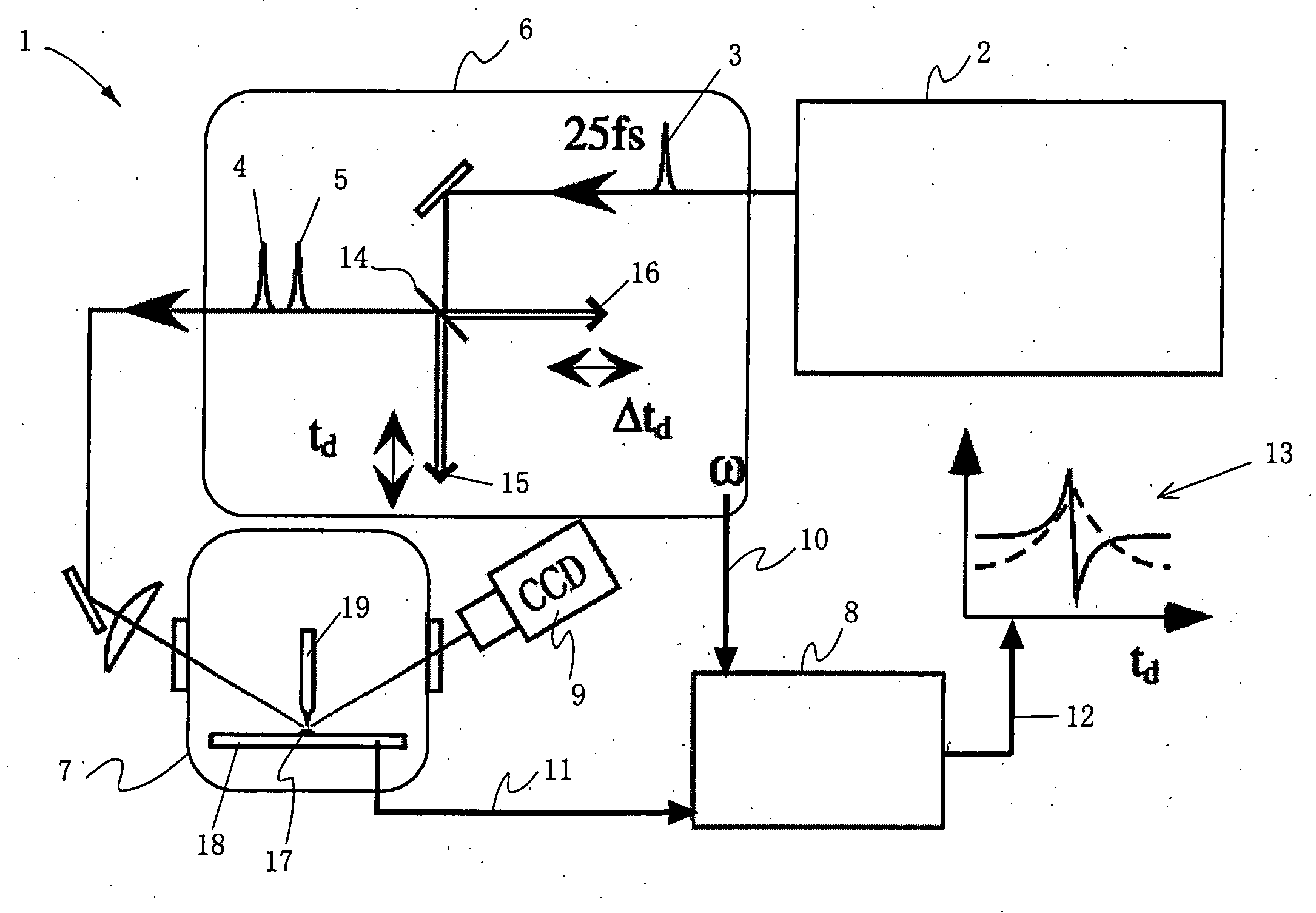
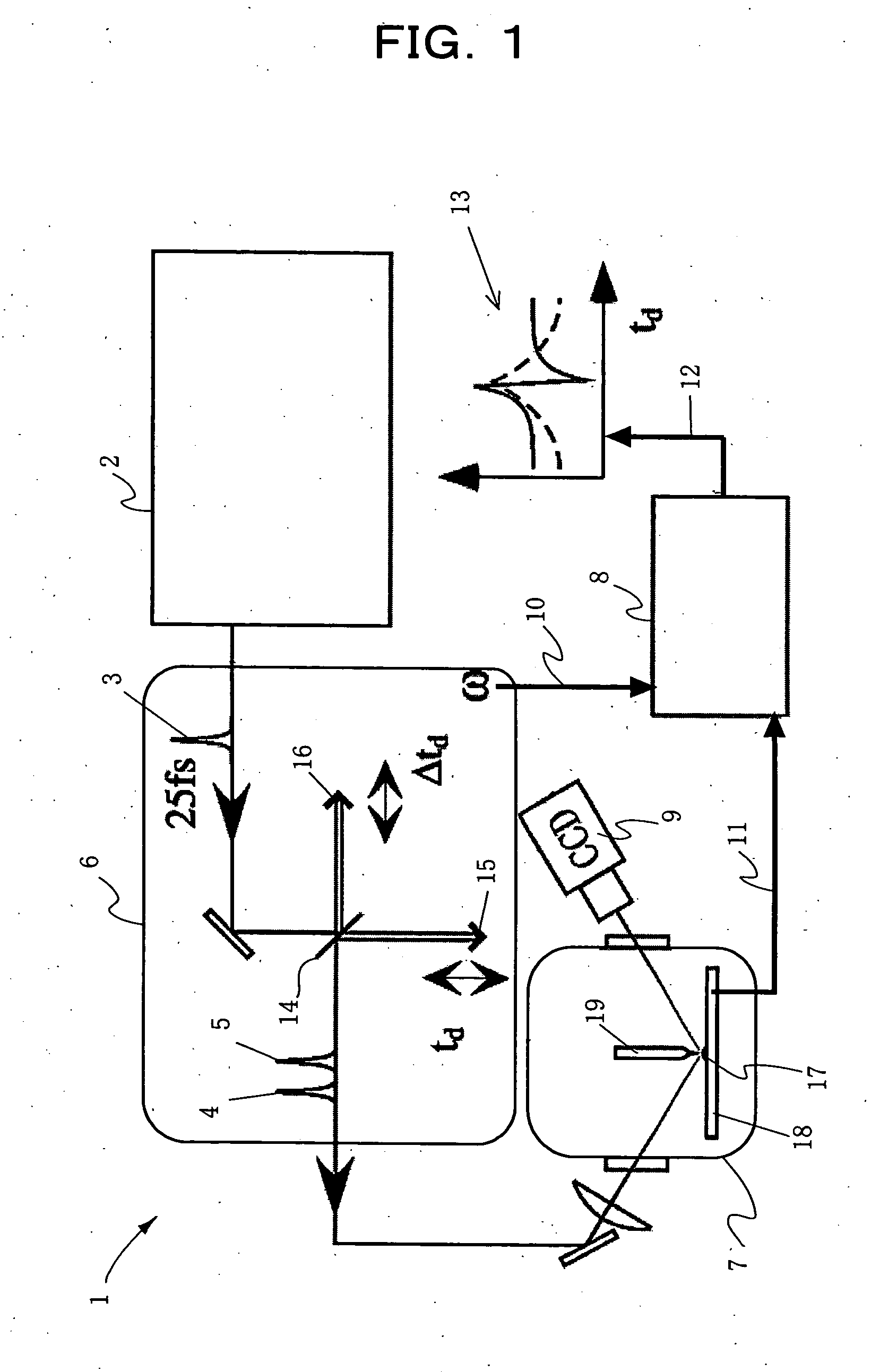
FIG. 1 is a diagram illustrating the construction of a delay time modulated and femtosecond time-resolved scanning probe microscope apparatus constituting a first form of implementation of the present invention. In the Figure, the delay time modulated and femtosecond time-resolved scanning probe microscope apparatus of the present invention designated by reference numeral 1 comprises an ultrashort laser pulse generator 2 for producing a series of ultrashort laser pulses 3; a delay time modulating circuit 6 which splits an ultrashort laser pulse 3 produced by the ultrashort laser pulse generator 2 into two ultrashort laser pulses 4 and 5 ...


PUM


Abstract

Disclosed is a measuring apparatus for a physical phenomenon by photoexcitation, in particular a delay time modulated and time-resolved, scanning probe microscope apparatus providing an ultimate resolution both temporal and spatial. The apparatus comprises an ultrashort laser pulse generator (2); a delay time modulating circuit (6) which splits an ultrashort laser pulse (3) produced by the ultrashort laser pulse generator (2) into two and which also modulates a delay time td between the two ultrashort laser pulses (4 and 5) with a frequency (ω); a scanning probe microscope (17); and a lock-in detection unit (8) which performs lock-in detection with the delay time modulation frequency (ω) of a probe signal (11) from the scanning probe microscope (17). It can detect the delay time dependency of the probe signal (11) as its differential coefficient to the delay time, with no substantial influence from fluctuations in the intensity of ultrashort laser pulses (3) while preventing the probe apex (19) from thermal expansion and shrinkage by repeated irradiation with ultrashort laser pulses (3). A photoexcited physical phenomenon dependent on a delay time between ultrashort laser pulses can thus be measured at a temporal resolution in the order of femtoseconds and at a spatial resolution in the order of angstroms.

Description

TECHNICAL FIELD The present invention relates to an apparatus for measuring a physical phenomenon by photoexcitation, which has an ultimate resolution both temporal and spatial. More specifically, the invention relates to a delay time modulated and time-resolved, scanning probe microscope apparatus. BACKGROUND ART Attempts to develop next-generation devices having unprecedented functions by controlling structures on nanoscale have been growing rapidly in late years. Among others, creating a functional device and an ultrafast device utilizing photophysical properties is one of particularly important targets. To this end, it becomes necessary and essential to elucidate a photoexcited physical phenomenon in a local area of nanoscale, including a transient response therein. In this connection, it has been proposed to introduce a new measurement technique that combines a scanning probe microscopic technique providing an ultimate spatial resolution with a laser pulse technique providing...

Claims


Application Information

Patent Timeline
IPC IPC(8): G01J1/42G01J3/28G01J3/433G01N21/64G01Q30/00G01Q30/02G01Q60/10G01Q60/24
CPCB82Y35/00G01J3/2889G01J3/433G01J2001/4242Y10S977/85G01N21/6458G01N2021/6415G01Q30/02G01N21/6408G01Q60/12
Inventor SHIGEKAWA, HIDEMITAKEUCHI, OSAMUYAMASHITA, MIKIOMORITA, RYUJI
Owner JAPAN SCI & TECH CORP
Why Eureka
Try Eureka