Low voltage low power bandgap circuit

a low-power, band-gap technology, applied in pulse manipulation, pulse technique, instruments, etc., can solve the problems of limited utility of brokaw cells and limited usefulness of low-voltage applications, and achieve low-voltage operating range, high loop gain, and reduced power consumption

Inactive Publication Date: 2005-02-17
TEXAS INSTR INC
View PDF4 Cites 17 Cited by
  • Summary
  • Abstract
  • Description
  • Claims
  • Application Information

AI Technical Summary

Benefits of technology

The invention provides bandgap circuits and methods with advantages including but not limited to a low voltage operating range, reduced power consumption, high loop gain, reduced chip area, and reduced cost. These and other features, advantages

Problems solved by technology

The Brokaw cell is relatively simple and accurate but its usefulness in low voltage applications is limited by its minimum supply voltage requirement,
Thus, the utility of the Brokaw cell is limited to applications where the minimum input vol

Method used


Image

  • Low voltage low power bandgap circuit
  • Low voltage low power bandgap circuit
  • Low voltage low power bandgap circuit

Examples


Embodiment Construction

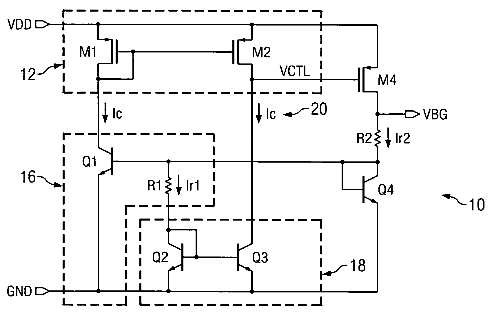
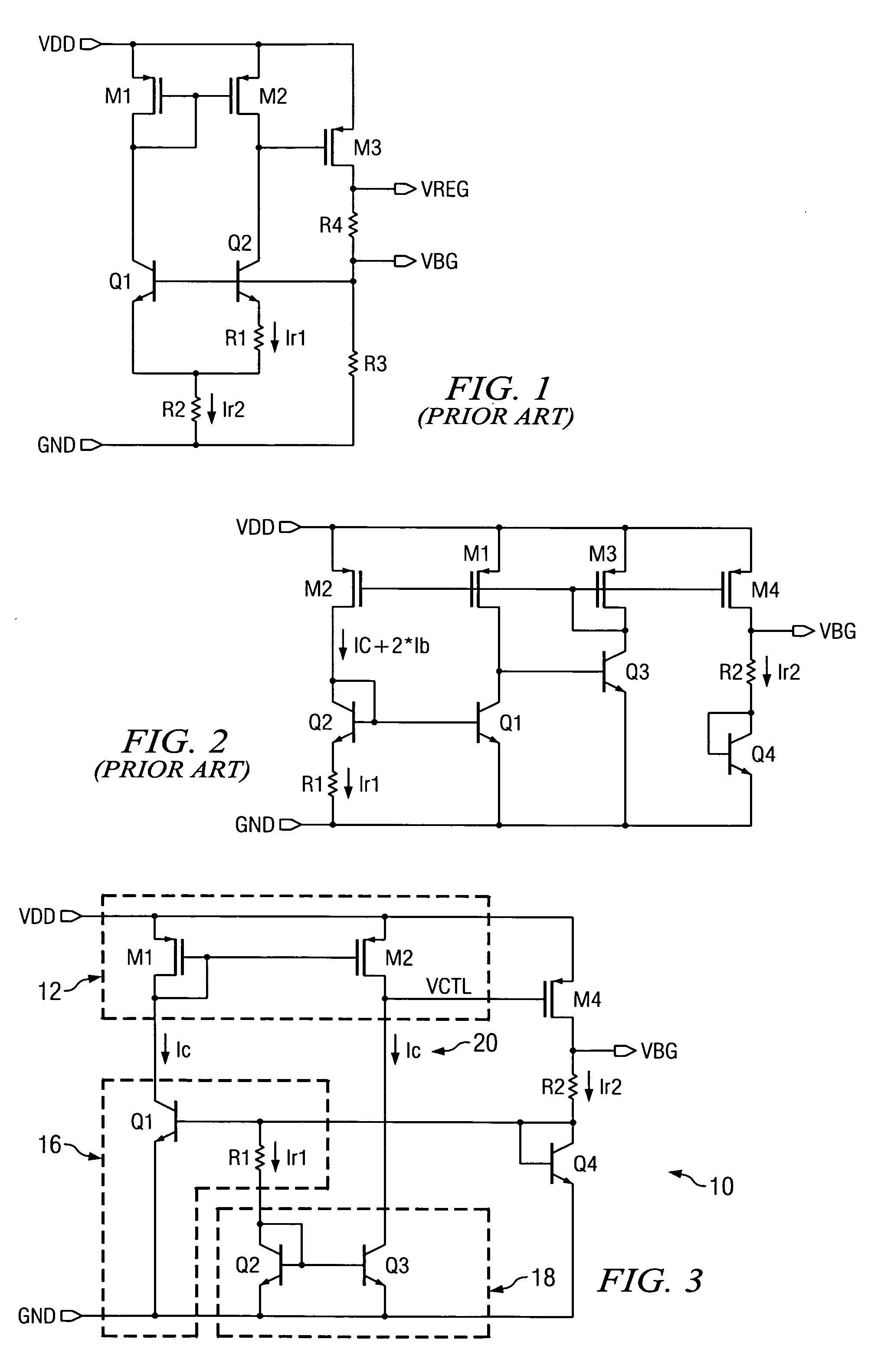
In general, the preferred embodiments of the invention provide bandgap reference circuits that operate at low supply voltages while providing good accuracy with little power consumption. First referring primarily to FIG. 3, a schematic diagram of a bandgap reference circuit 10 according to the invention is shown. For the purposes of providing a context for illustrating the invention, it is assumed that a supply voltage VDD and ground exist in a given electronic circuit or system. Further assuming that it is desired to provide a bandgap reference voltage VBG, the bandgap reference circuit 10 has a first current mirror circuit 12 electrically connected to the supply voltage VDD such that a current, labeled Ic, is produced. Typically, the first current mirror 12 is constructed from first M1 and second M2 field-effect transistors as is known in the arts. Those skilled in the arts will appreciate that variations from the first current mirror circuit 12 shown may be made without departin...


PUM


Abstract

Disclosed are methods and circuits for providing a bandgap reference in an electronic circuit having a supply voltage and ground. The methods include steps for generating a bandgap reference current, mirroring the bandgap reference current, summing the mirrored currents, and modulating and outputting a bandgap reference voltage from the sum. Representative preferred embodiments are disclosed in which the methods of the invention are used in providing under-voltage protection and in providing a regulated output voltage. Circuits are disclosed for a bandgap reference voltage generator useful for providing a bandgap reference voltage in a circuit. A first current mirror for provides current from a supply voltage. A bandgap reference current circuit between the first current mirror and ground is configured for deriving a bandgap current proportional to absolute temperature. A second current mirror and control circuit are provided for summing the mirrored currents and modulating a bandgap reference voltage output. Preferred embodiments of the invention include a bandgap under-voltage detection circuit using a comparator and a voltage regulator circuit having a regulated voltage output capability.

Description

TECHNICAL FIELD The invention relates to reference voltage circuits for IC devices. More particularly, the invention relates to methods and circuits for a bandgap reference generator. BACKGROUND OF THE INVENTION Bandgap reference circuits are well known in the analog IC arts for generating a reference voltage based on the bandgap potential inherent in semiconductor materials, generally approximately 1.2 Volts. As IC technology shrinks in size with advances in semiconductor process technology, device supply voltages must inevitably be reduced accordingly to avoid breakdown of the devices. For ICs used in portable electronics, minimal power consumption is also highly desirable. Significant effort is therefore devoted to development of low voltage and low power IC design. Bandgap reference circuits are widely used to provide an accurately known voltage as a fundamental reference for other analog circuit blocks and for generating a bias current or reference current. Since bandgap refe...

Claims


Application Information

Patent Timeline
IPC IPC(8): G05F3/30
CPCG05F3/30
Inventor XI, XIAOYU
Owner TEXAS INSTR INC
Why Eureka
Try Eureka