Optical element having minute periodic structure

a technology of periodic structure and optical element, which is applied in the direction of mountings, coatings, instruments, etc., can solve the problems of large stress at the interface between the glass and the resin layer, the cost of aspheric lenses manufactured through glass grinding, and the limited types of glass materials that can be used, etc., to achieve stable and favorable reflection suppressing

Active Publication Date: 2005-02-17
CANON KK
View PDF7 Cites 49 Cited by
  • Summary
  • Abstract
  • Description
  • Claims
  • Application Information

AI Technical Summary

Benefits of technology

It is a subject of the present invention to provide an optical element which is resistant to changes in environme...

Problems solved by technology

Aspheric lenses manufactured through the glass grinding are significantly expensive since each machining takes a long time, although high flexibility is provided in optical design with few limitations on types and sizes of glass materials of the lenses.
Aspheric lenses formed through the glass molding are relatively inexpensive since they can be manufactured with molds, but only limited types of glass materials can be used.
When the environmental temperature for the replica lens is changed, however, a large difference between the linear expansion coefficient of the base glass and the linear expansion coefficient of the resin results in large stress at the interface between the glass and the resin layer.
If the environmental temperature is changed, complicated and large stress is produced at the surface (the aspherical surface) of the resin since the linear expansion coefficient of the resin is...

Method used


Image

  • Optical element having minute periodic structure
  • Optical element having minute periodic structure
  • Optical element having minute periodic structure

Examples


embodiment 1

(Embodiment 1)

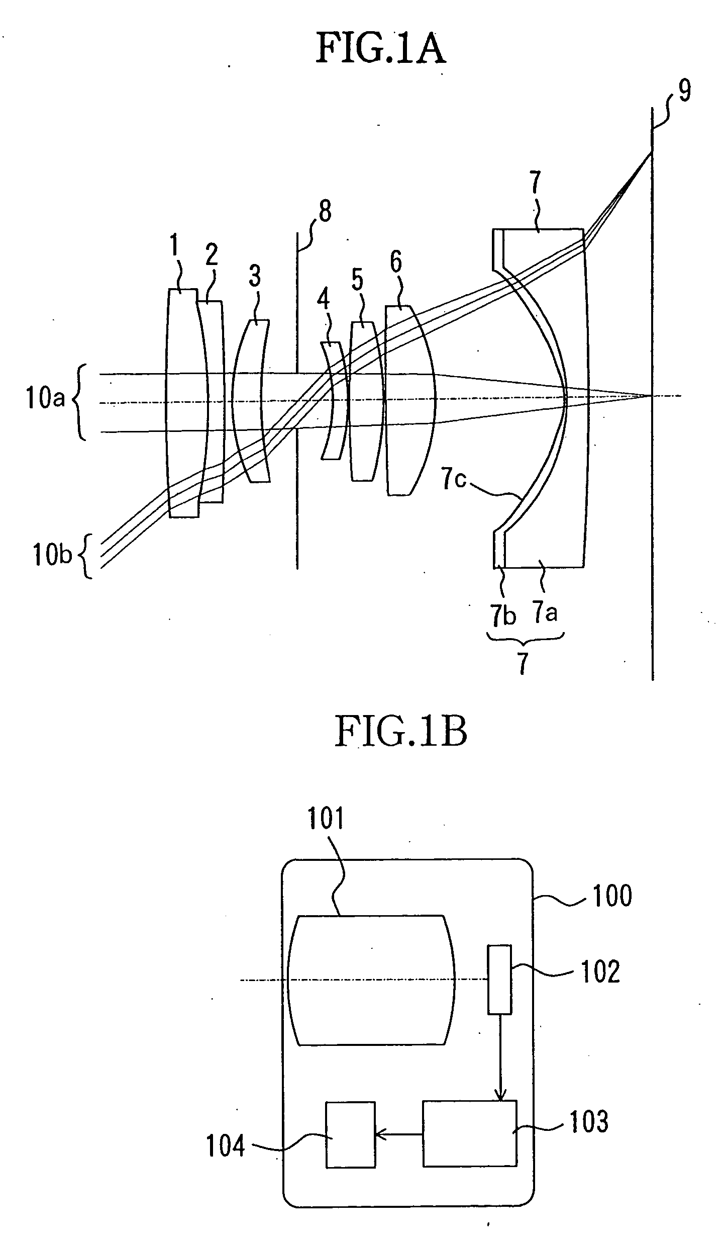
FIG. 1A shows an image-taking optical system which is Embodiment 1 of the present invention. FIG. 1B shows the structure of an image-taking apparatus such as a digital camera and a video camera which uses the image-taking optical system.

In FIG. 1B, reference numeral 100 shows a body of the image-taking apparatus, and 101 the image-taking optical system. Reference numeral 102 shows an image-pickup element formed of a CCD sensor, a CMOS sensor or the like disposed on an image plane of the image-taking optical system 101. The image-pickup element 102 photoelectrically converts a subject image formed by the image-taking optical system 101. An output signal from the image-pickup element 102 is amplified and A / D converted by an image processing circuit 103 before predetermined processing thereby. In this manner, an image signal is produced. The image signal is recorded on a recording medium 104 such as a semiconductor memory, an optical disc, and a magnetic tape.

In FIG. ...

embodiment 2

(Embodiment 2)

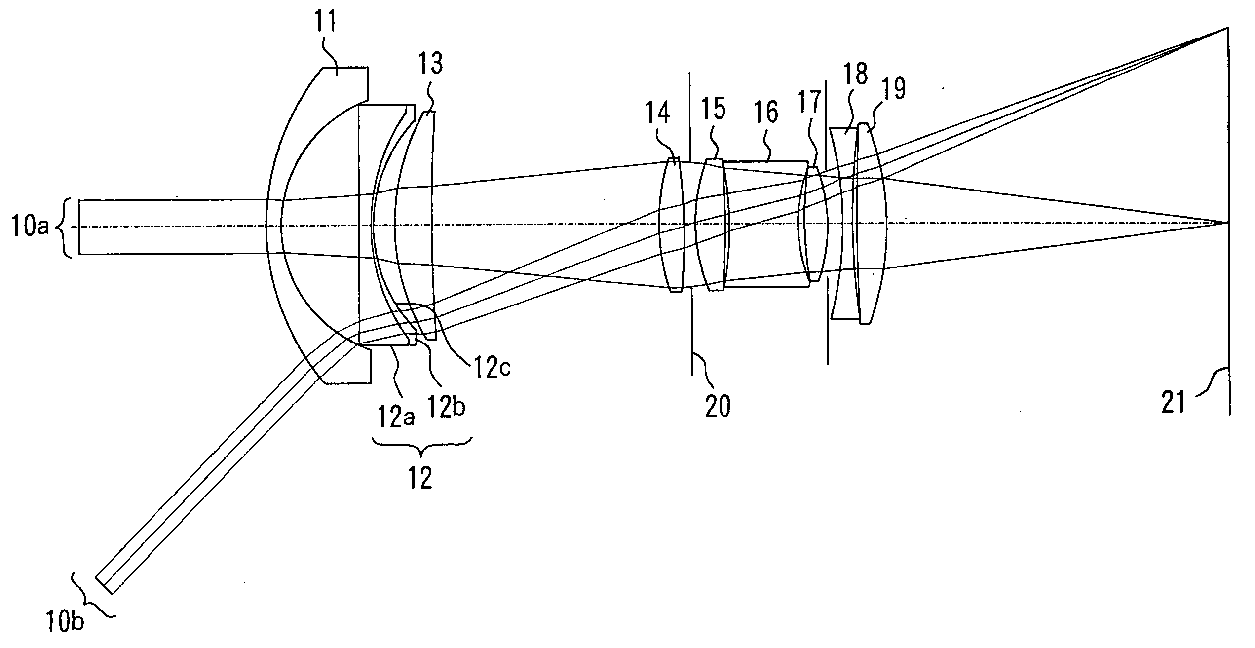
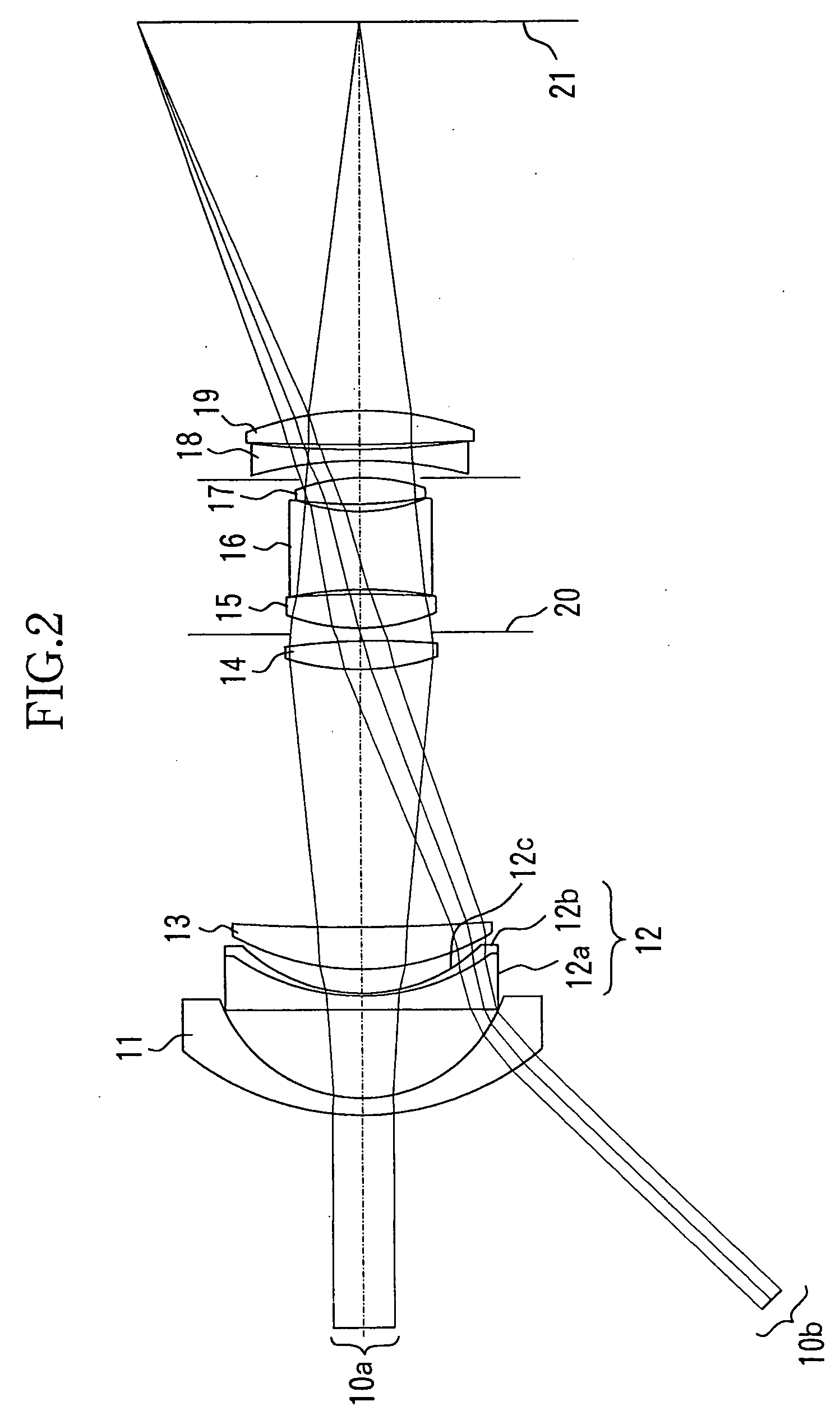
FIG. 2 shows an image-taking optical system which is Embodiment 2 of the present invention. The image-taking optical system is also used in the image-taking apparatus shown in FIG. 1B. In FIG. 2, reference numerals 11 to 19 show lenses constituting the image-taking optical system, 20 a stop, and 21 an image plane.

Reference numeral 10a shows a luminous flux (a central luminous flux) which is formed into an image at the center of the image plane 21, while reference numeral 10b shows a luminous flux (a peripheral luminous flux) which is formed into an image in a peripheral portion.

Of the lenses 11 to 19, the lens 12 is an aspheric lens having an aspherical surface on the image forming side. The lens 12 is a replica aspherical surface formed of a glass lens (a base member) 12a which has spherical surfaces on both sides and a relatively thin resin layer 12b which is formed with the replica method on the spherical surface on the image plane side of the glass lens 12a and...

embodiment 3

(Embodiment 3)

FIG. 8 shows an image-taking optical system which is Embodiment 3 of the present invention. The image-taking optical system is also used in the image-taking apparatus shown in FIG. 1B. In FIG. 8, reference numerals 31 to 39 show lenses constituting the image-taking optical system, 40 a stop, and 41 an image plane.

Reference numeral 10a shows a luminous flux (a central luminous flux) which is formed into an image at the center of the image plane 41, while reference numeral 10b shows a luminous flux (a peripheral luminous flux) which is formed into an image in a peripheral portion.

Of the lenses 31 to 39, the lens 32 is an aspheric lens having an aspherical surface on the image plane side. The lens32 is a so-called replica aspherical surface formed of a glass lens (a base member) 32a which has spherical surfaces on both sides and a relatively thin resin layer 32b which is formed with the replica method on the spherical surface on the image plane side of the glass lens ...


PUM

PropertyMeasurementUnit
Angleaaaaaaaaaa
Nanoscale particle sizeaaaaaaaaaa
Structureaaaaaaaaaa

Abstract

An optical element is disclosed which is resistant to changes in environmental characteristics such as temperature and humidity and achieves a stable and favorable reflection suppressing effect. The optical element has a base member and a resin layer which is formed on the base member and has a linear expansion coefficient different from that of the base member. The resin layer has a minute periodic structure which has a period smaller than the wavelength of incident light on the optical element.

Description

BACKGROUND OF THE INVENTION 1. Field of the Invention The present invention relates to an optical element having a minute periodic structure. 2. Description of the Related Art Spherical lenses or aspheric lenses are used in an image-taking optical system of an image-taking apparatus such as a video camera and a digital still camera and in a projection optical system of a liquid crystal projector or the like. Manufacturing methods of the aspheric lenses include a glass grinding method, a glass molding method, a plastic molding method, a replica method (a molding and transfer method). Aspheric lenses manufactured through the glass grinding are significantly expensive since each machining takes a long time, although high flexibility is provided in optical design with few limitations on types and sizes of glass materials of the lenses. Aspheric lenses formed through the glass molding are relatively inexpensive since they can be manufactured with molds, but only limited types of g...

Claims


Application Information

Patent Timeline
IPC IPC(8): G02B1/04G02B1/11G02B3/00G02B3/02G02B5/18
CPCG02B5/1814
Inventor SAITO, HIROSHI
Owner CANON KK
Why Eureka
Try Eureka