Dialysis valve and method

a technology of dialysis valve and valve body, which is applied in the field of valves, can solve the problems of intimal hyperplasia, progressive stenosis, and compromise of the lumen of the gra

Active Publication Date: 2005-02-17
INTERRAD MEDICAL
View PDF17 Cites 24 Cited by
  • Summary
  • Abstract
  • Description
  • Claims
  • Application Information

AI Technical Summary

Benefits of technology

In another embodiment the invention comprises a dialysis valve, the valve comprising a tube capable of containing fluids and defining a longitudinal dimension, a diameter and an inner surface. A bellows capable of being held at varying lengths defines an interior chamber wherein the tube is mounted in the chamber so that when the bellows increases in length, the tube simultaneously increases in longitudinal dimension and at least a portion of the tube decreases in diameter. In a further embodiment the tube comprises a braided nitinol structure processed to exhibit superelasticity below normal human body temperature coated with an elastomer allowing the tube to be repeatedly altered in longitudinal dimension and in diameter and still maintain fluid containing capability.
In an alternative embodiment the invention comprises a valve, the valve comprising a tube capable of containing fluids and defining a longitudinal dimension, a diameter and an inner surface. A nitinol spring is attached to each end of the tube so that when the spring is actuated the tube decreases in longitudinal dimension and the tube increases in diameter. In a further embodiment the tube comprises a braided nitinol structure processed to exhibit superelasticity below normal human body temperature coated with an elastomer allowing the tube to be repeatedly altered in longitudinal dimension and in diameter and still maintain fluid containing capability.

Problems solved by technology

Dialysis is usually necessary every two to three days, which often results in the lumen of the graft becoming compromised.
The more common problem related to dialysis grafts is intimal hyperplasia, which can occur when the higher pressure / volume of the arterial flow crosses the boundary from the relatively non-compliant graft to the more compliant outflow vein at the venous anastomosis.
The resultant intimal hyperplasia in the vein adjacent to the anastomosis leads to progressive stenosis and eventually premature clotting and graft occlusion.
It is known that blood flow in excess of 300 cc per minute can cause intimal hyperplasia in the outflow vein near the anastomosis.
The problem arises from the fact that blood flows less than 300 cc per minute have been associated with graft thrombosis.

Method used


Image

  • Dialysis valve and method
  • Dialysis valve and method
  • Dialysis valve and method

Examples


Embodiment Construction

Definitions

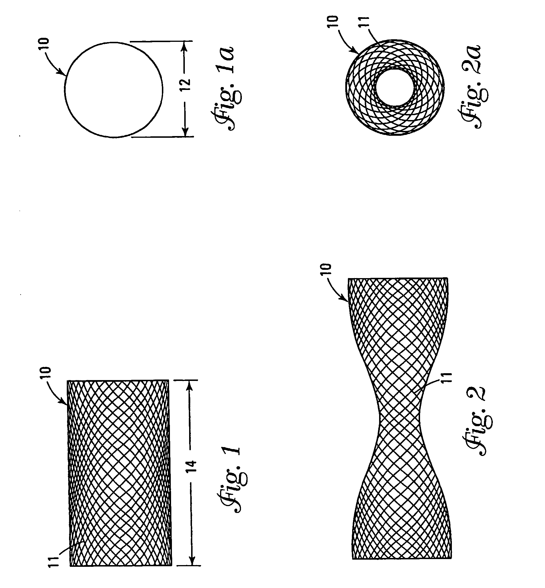
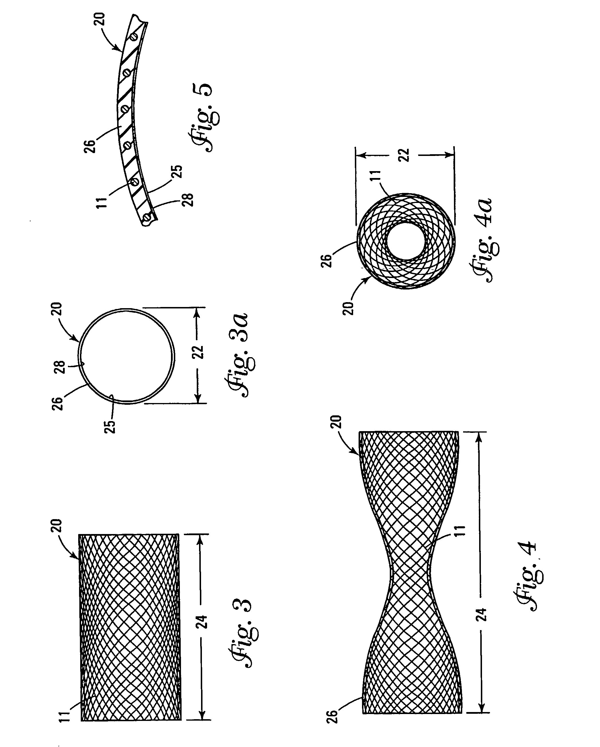
“Braid Assembly” refers to a tubular structure comprised of overlapping flexible strands. “ePTFE” refers to Expanded Polytetrafluoroethylene.

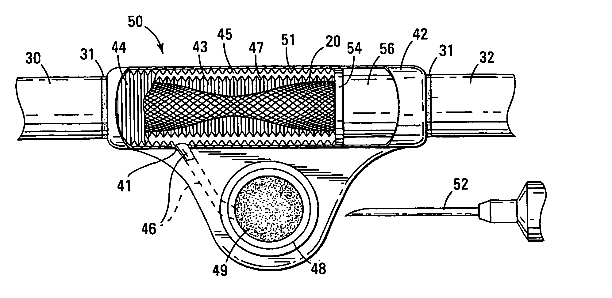
Nomenclature 10 Uncoated Braid 11 Strand 12 Diameter 14 Longitudinal Dimension 20 Coated Braid Assembly 22 Diameter 24 Longitudinal Dimension 25 Inner Surface 26 Elastomeric Coating 28 Anti-Thrombogenic Coating 30 Fistula Graft (Arterial Side) 31 Bonding Area 32 Fistula Graft (Venous Side) 41 Aperture 42 Outer Housing 43 Chamber 44 Bellows 45 Inter-Wall Space of Bellows 46 Hydraulic Line 47 Inner Wall of Bellows 48 Port 49 Membrane 50 Dialysis Valve (Hydraulic Bellows Actuated) 51 Outer Wall of Bellows 52 Infusion Needle 53 Nipple 54 Floating Connector 55 Fixed Connector 56 Compressible Section 60 Dialysis Valve (Hydraulic Balloon Actuated) 62 Balloon 64 Hydraulic Line 80 Valve 82 Nitinol Spring 83 O Ring 84 Controller 84a Electrical Wire (Signal) 84b Electrical Wire (Ground) 85 Threaded Connector 86 Outer Housing 100 Arm 110 Art...


PUM


Abstract

A dialysis valve includes a tube attached between an artery and a vein which, when elongated, simultaneously narrows in diameter at at least one location. The narrowed portion of the tube decreases the volume and velocity between the arterial and venous side of the patient to prevent damage or intimal hyperplasia on the venous side between dialysis treatments. When the valve is opened for dialysis, an unrestricted blood flow exists between the arterial and venous side, permitting a controlled, open blood flow during dialysis.

Description

FIELD OF THE INVENTION The present invention relates to a valve useful for controlling blood flow in artificial dialysis fistulas or bypass grafts. BACKGROUND Dialysis involves connecting patients with insufficient kidney function to a dialysis machine which cleanses the blood of waste products and impurities. Put another way, the dialysis machine performs the same function as a normal, healthy kidney should. In other cases, dialysis is used to remove poisons and drugs from the blood more safely and quickly than the natural kidneys would. To properly connect a patient to a dialysis machine requires accessing, on a continuing basis, a blood vessel, to divert the flow of blood from the patient to the dialysis machine. This is normally accomplished by the implantation into the patient of an artificial fistula or bypass graft, which is usually made of expanded polytetrafluoroethylene (ePTFE). In the case of a graft, the graft is punctured with a needle and blood from patients requirin...

Claims


Application Information

Patent Timeline
Patent Type & Authority Applications(United States)
IPC IPC(8): A61MA61M1/36A61M5/00A61M39/10A61M39/22
CPCA61M1/3655A61M2205/0266A61M39/228A61M39/22
Inventor CLAUDE, TIMOTHY J.BARLOW, EDWARD A.HUNTER, DAVID W.ROSENBERG, MICHAEL S.
Owner INTERRAD MEDICAL
Why Eureka
Try Eureka