
Load distribution method and client-server system

a load distribution and client-server technology, applied in the direction of digital transmission, securing communication, instruments, etc., can solve the problems of imposing an upper limit on the number of requests transmissible out to the added server, the time that the newly added server takes to process requests cannot be prevented, and the load results are uneven among the servers

Inactive Publication Date: 2005-02-17
HITACHI LTD
View PDF8 Cites 92 Cited by
  • Summary
  • Abstract
  • Description
  • Claims
  • Application Information

AI Technical Summary

Benefits of technology

[0017] In the present invention, right after a new server is added to the server cluster, loads are distributed in a special way. That is to say, the number of requests transmissible out to a newly added server having a performance (or a processing power) lower than any already existing server is set at a value small in comparison with a value set for the number of requests transmissible out to every other already existing server. Thus, the time that the added server takes to process requests can be prevented from becoming long.
[0019] The present invention is characterized in that the load control program adjusts the number of requests to be output to a newly added server by setting the number of requests transmissible out to the added server at a value small in comparison with a value set for the number of requests transmissible out to every already existing server right after addition of the new server to the server-cluster system and, with the lapse of time, increasing the number of requests transmissible out to the added server step by step.
[0021] The load control program increases the number of requests transmissible out to the added server step by step. There are 2 methods for computing an increment for the number of requests. In accordance with one of the methods, information on performance is obtained from the added server to be used in the computation of the increment. In accordance with the other method, on the other hand, no information is acquired from the added server.
[0022] In order to use performance information obtained from the server-cluster system in the computation of the increment for the number of requests to be transmitted out to the added server, the load control program is provided with a function to acquire performance information and a function to compute the increment on the basis of the information on performance. The information on performance includes a cache hit rate and the length of a queue of requests each waiting for a processing turn from the added server. Then, the load control program increases the number of requests on the basis of the computed increment.
[0023] If no performance information obtained from the added server is used in the computation of the increment for the number of requests to be transmitted out to the added server, on the other hand, the load control program increases the number of requests in accordance with a rule set in advance. For example, the load control program increases the number of requests by 10% per 10 seconds during a predetermined period of time lapsing since the addition of the added server to the server-cluster system.
[0024] As described above, the present invention provides a load distribution method adopted by a client-server system comprising a plurality of clients and a server cluster, which comprises a plurality of servers used for processing requests made by the clients and is used for dynamically changing the number of servers operating therein. The load distribution method is characterized in that the clients each monitor the number of servers composing the server cluster and, right after an increase in server count is detected as an increase caused by addition of a new server, the number of requests transmissible out to the newly added server is set at a value small in comparison with a value set for the number of requests transmissible out to every other server, and requests are output to the servers on the basis of the set values. Thus, the time that the newly added server takes to process requests can be prevented from becoming long when the new server is added to the server-cluster system.

Problems solved by technology

If an inappropriate load distribution algorithm is adopted, requests made by the clients are not distributed equally among the servers so that an imbalance of loads results among the servers.
The processing time of a server bearing a heavy load to process requests increases substantially in comparison with a server bearing a light load so that the processing of a request cannot be completed in time.
If the slow start mechanism is used, however, an upper limit is imposed on the number of requests transmissible out to the added server during a predetermined period of time following the addition of the new server.
If the cluster reconfiguration technology described above is adopted in conjunction with an improper load distribution algorithm, nevertheless, an imbalance of loads may result among servers composing a server-cluster system when a new server is added to the server-cluster system.
This imbalance of loads among servers is caused by a difference in request-processing power between the server newly added to the server-cluster system by adoption of the cluster reconfiguration technology and existing servers already operating in the server-cluster system.
Thus, the time it takes to respond to the request made by the user of services is short.
Thus, the time it takes to respond to the request made by the user of services is long.
As a result, the time it takes to respond to the request made by the user of services is long.
Thus, for such an existing cache server, the time it takes to respond to the request made by the user of services is short in comparison with the newly added cache server.
If the round-robin method described above is adopted to output as many requests to a newly added cache server as requests transmissible out to every already existing cache server having a big difference in power to process requests made by a user of services from the newly added cache server, the newly added cache server is not capable of completing the requests in time so that, in the newly added cache server, there is resulted in a long queue of requests each waiting for a processing turn.
As a result, a long response-time delay is incurred, causing disadvantages to the user of services and hence betraying the trust of the user of services.

Method used


Image

  • Load distribution method and client-server system
  • Load distribution method and client-server system
  • Load distribution method and client-server system

Examples


first embodiment

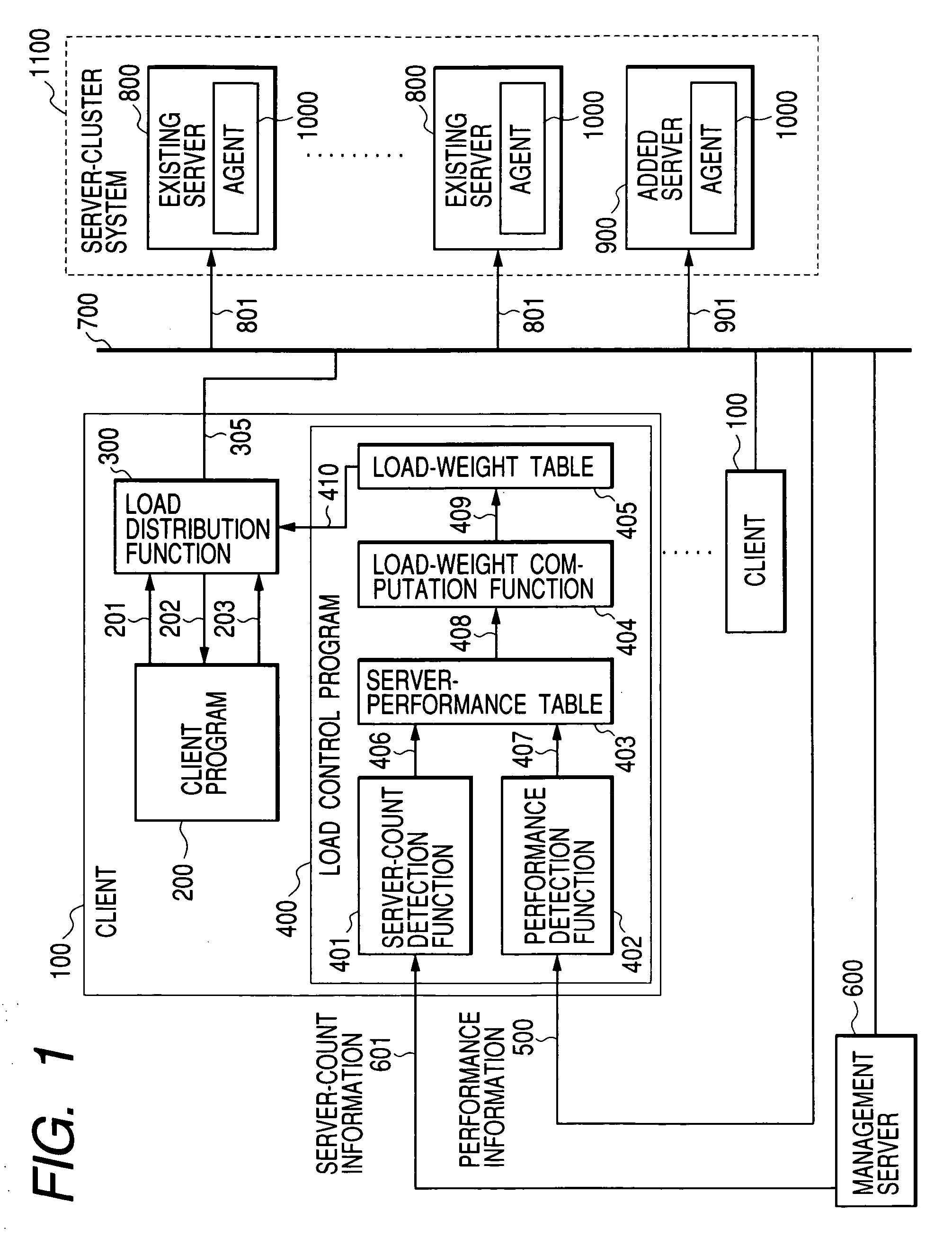
[0040]FIG. 1 is a block diagram showing a rough configuration of a client-server system implemented by the present invention. The client-server system implemented by this embodiment comprises a plurality of clients 100 and a server-cluster system 1100 connected to the clients 100 by an inter-server network 700. A client 100 transmits a request to the server-cluster system 1100 as a request for a service, and receives a result of the request from the server-cluster system 1100. In the client 100, a load distribution program 300 and a load control program 400 are executed. It is to be noted that a request made by the client 100 and transmitted to the server-cluster system 1100 as a request for processing of a service is also referred to hereafter as an output request.

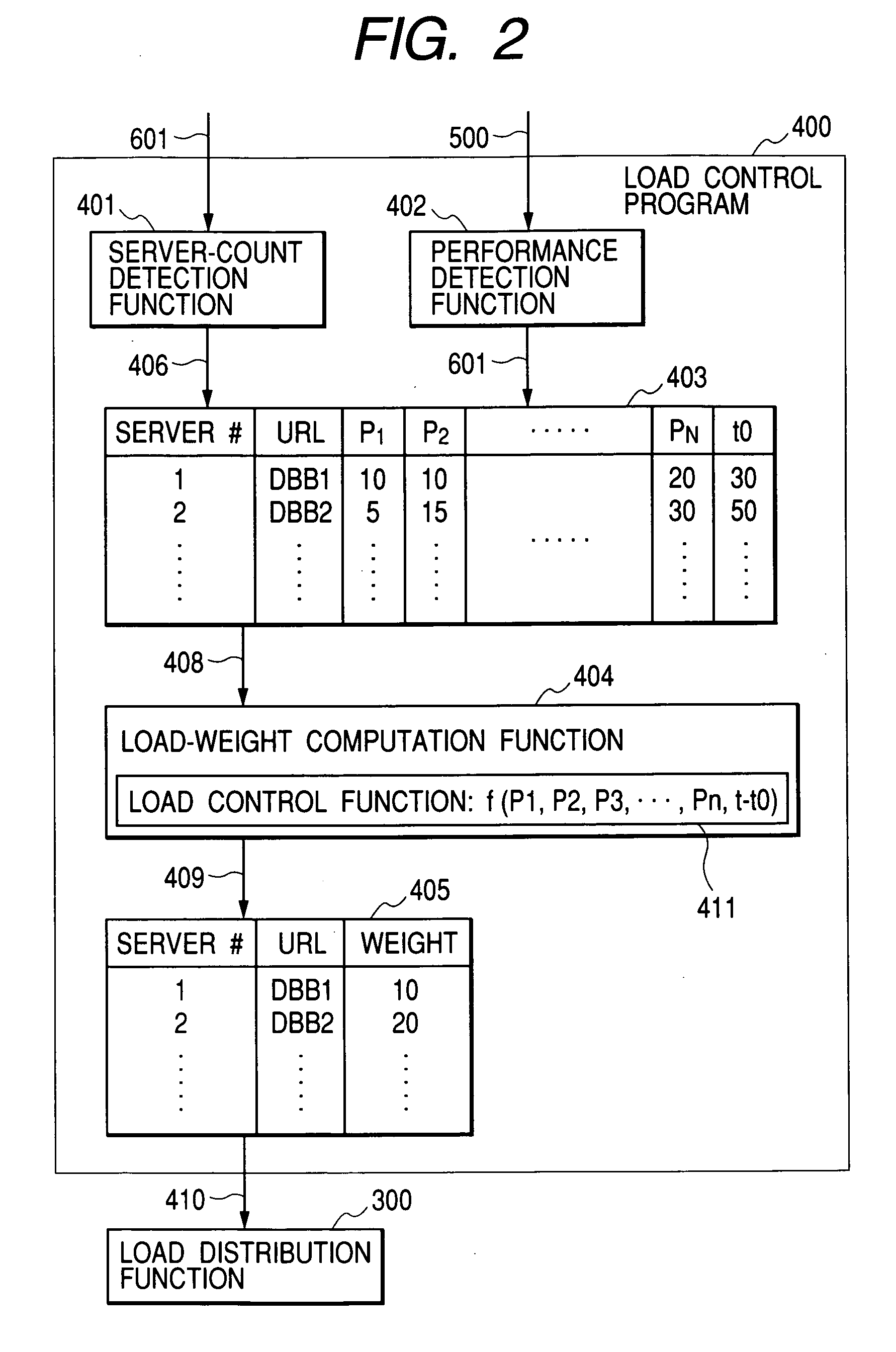
[0041] The load control program 400 creates a load-weight table 405, which contains data used by the client 100 to determine the number of requests to be assigned and transmitted out to each of the servers composing the s...

second embodiment

[0116] As explained so far, when a new directory server 2200 is added to the directory-server-cluster system 2600 handling each request made by a client 2000 as a request for acquisition of a file and, hence, changes the configuration of the directory-server-cluster system 2600 in the storage system implemented by the present invention, the number of files stored in a storage apparatus 2300 as files, of which the newly added directory server 2200 serves as a new designated directory server taking charge, is set at a value small in comparison with that set for each other already existing directory server 2100. By setting the number of such files at a small value, the processing carried out by the newly added directory server 2200 can be prevented from becoming stagnant and the processing efficiency of the directory-server-cluster system 2600 as a whole can thus be increased.

[0117] In the first and second embodiments described so far, the client 100 and the client 2000 respectively co...


PUM


Abstract

A load distribution method is adopted by a client-server system comprising a plurality of clients 100 and a server cluster 1100, which includes a plurality of servers 800 each used for processing requests made by the clients 100 and allows the number of the servers 800 to be changed dynamically. Each of the clients 100 detects the number of servers 800 composing the server cluster 1100, sets an allocation of requests transmissible out to a newly added server 900 at a value small in comparison with that set for each of the other servers 800 right after detecting an increase in server count and then transmits out requests to the servers on the basis of the set allocation. It is thus possible to provide the clients 100 and the server-cluster system 1100 with the load distribution method suitable for a cluster reconfiguration technology for changing the number of servers composing the server-cluster system 1100 in accordance with an increase and a decrease in demand for a service.

Description

FIELD OF THE INVENTION [0001] The present invention relates to a load distribution method provided as a method for distributing loads of rendering services requested by clients among servers composing a server-cluster system and as a method suitable for a cluster reconfiguration technology for changing the number of servers composing the server-cluster system in accordance with an increase and a decrease in demand for services in a client-server system utilizing, among others, the server-cluster system serving as a system for processing services demanded by users of services and for constructing services such as electronic business transactions using the Internet, and relates to the client-server system adopting the load distribution method. [0002] The present invention is particularly useful when applied to distribution of loads between upstream and downstream servers in a hierarchical web system for processing loads in accordance with a hierarchical structure such as a sequence of...

Claims


Application Information

Patent Timeline
Patent Type & Authority Applications(United States)
IPC IPC(8): H04L29/06H04L29/08
CPCH04L29/06H04L2029/06054H04L67/1023H04L67/1002H04L67/1008H04L67/10015H04L67/1001H04L9/40
Inventor MASUDA, MINEYOSHITARUI, TOSHIAKIHIGUCHI, TATSUO
Owner HITACHI LTD
Learn More